Current converter circuit

A circuit and converter technology, applied in the field of converter circuits, can solve the problems of limited energy storage capacity, incompatibility, inconvenience to expand capacity, etc., and achieve the effect of improving DC current and large energy storage capacity

Active Publication Date: 2011-01-19
ELECTRIC POWER RES INST OF GUANGXI POWER GRID CO LTD
View PDF0 Cites 0 Cited by
  • Summary
  • Abstract
  • Description
  • Claims
  • Application Information

AI Technical Summary

Problems solved by technology

[0003] (1) The energy storage capacity is limited, so it cannot effectively suppress the fluctuation of transmission power
[0004] (2) It is inconvenient to expand the capacity by increasing the current, and it is not suitable for high-current and low-voltage power transmission, such as superconducting power transmission

Method used


Image

  • Current converter circuit
  • Current converter circuit
  • Current converter circuit

Examples


Embodiment Construction

[0029] The present invention is described in detail below in conjunction with accompanying drawing:

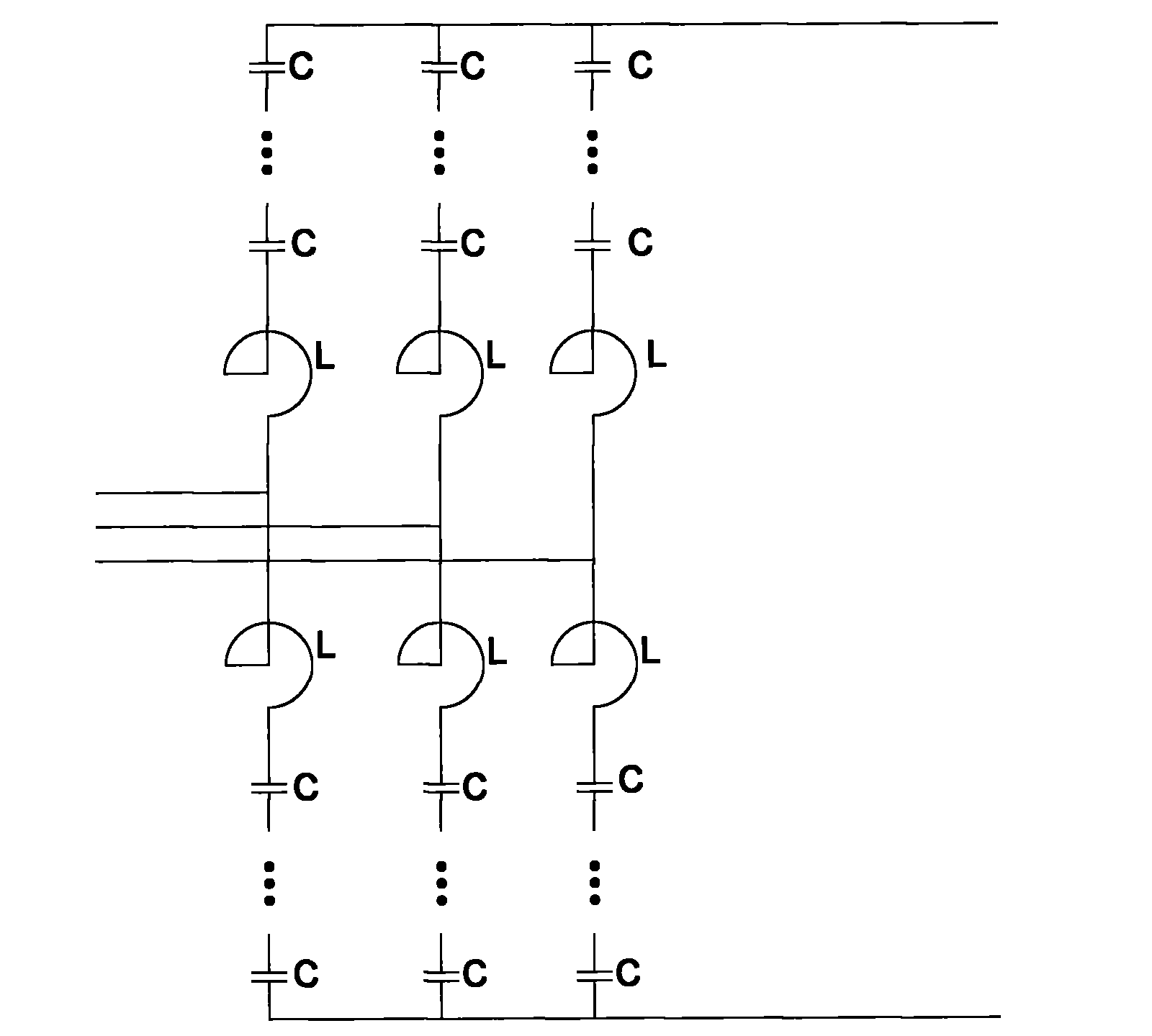
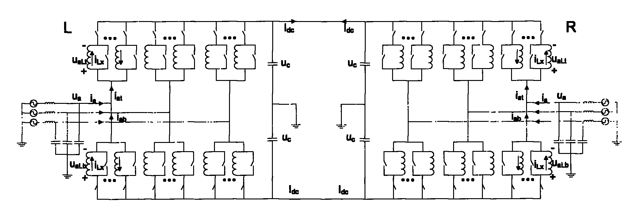
[0030] Such as image 3 with Figure 4 As shown, the present invention includes six bridge arms, and each bridge arm is composed of two inductance modules connected in parallel, wherein two terminals T1 and T2 are connected with the primary circuit, that is, the main circuit of the converter circuit, and the other terminal Ctrl is an optical signal Control terminals, the common ends of the inductance modules of each two bridge arms are connected together and connected to one phase of the three-phase AC circuit, and the other end of the inductance module of each bridge arm is connected to the main circuit through the IGBT and the positive pole of the DC side or The negative poles are connected, and the DC side of the converter circuit is connected with a voltage stabilizing capacitor. The inductance coil in each inductance module may be a superconducting material.

[0031] E...


PUM


Abstract

The invention relates to a convertor circuit which comprises six bridge arms. Each bridge arm comprises at least two inductive modules which are connected in parallel. The inductive module has three terminals connected with external circuit, in which two terminals are connected with primary circuit and another terminal is the control terminal of optical signal. Common terminals on the inductive module of every two bridge arms are connected together and are connected with one phase of three-phase AC circuit. Other terminal on the inductive module of each bridge arm is connected with anode or cathode on DC side through self-shutoff power electronic device. The DC side of the convertor circuit is connected with voltage regulation capacitor. The invention can independently control active power or reactive power on DC side and of having better ability to store energy. Cushion smoothing adjustment can be performed for wind energy or solar energy which has the output characterized by chance fluctuation by the invention providing an approach for synchronization. Modular structure is convenient to improve DC and provides a topology structure with practical value for the application of superconducting transmission of heavy current. The invention meets the requirements on the transmission and distribution, the power quality and the ecological environment in modern society.

Description

technical field [0001] The invention belongs to energy technology, and in particular relates to a converter circuit in the grid-connected or transmission process of various electric energies. Background technique [0002] The basis of the present invention is two kinds of converter circuits in the prior art: a two-level voltage source converter circuit and a multi-level voltage source converter circuit, and the converter circuit is also called converter topology. The two-level voltage source converter circuit uses pulse width modulation to control the output voltage waveform. The converter circuit is as follows: figure 1 shown. Among them, IGBT1-6 are insulated gate bipolar transistors. The multi-level voltage source converter circuit controls the output voltage waveform in a multi-level form. Inverter circuit such as figure 2 shown. Among them, C is a capacitor module with controllable switching, and L is a reactor. The two topologies can meet the flexible control of...

Claims


Application Information

Patent Timeline
Patent Type & Authority Patents(China)
IPC IPC(8): H02M3/06H02M3/10
Inventor 张翌晖唐跃进
Owner ELECTRIC POWER RES INST OF GUANGXI POWER GRID CO LTD
Why Eureka
Try Eureka