Lightning current waveform forming inductor
A lightning current and waveform technology, applied in the field of lightning current waveform forming inductance, can solve the problems of spark discharge at the connection, discharge at the connection, breakage, etc., and achieve the effect of stable and reliable operation and large current capacity.
Inactive Publication Date: 2011-01-05
XI AN JIAOTONG UNIV
View PDF0 Cites 0 Cited by
- Summary
- Abstract
- Description
- Claims
- Application Information
AI Technical Summary
Problems solved by technology
However, under the action of 10 / 350μs and 8 / 20μs strong lightning current, the waveform-forming inductance made by traditional inductance coil taps will have some defects: first, the connection is unreliable, and the connection is sparked and discharged; second, the connection is very unstable. convenient
Therefore, the 10 / 350μs and 8 / 20μs lightning current circuits have the following requirements for the waveform forming inductor: first, the waveform forming inductor must have a certain flow capacity; second, the early connection of the waveform forming inductor is not allowed to discharge and spark Third, the waveform forming inductance must be easily adjustable, so it is quite difficult to manufacture a lightning current waveform forming inductance with a large current capacity and easy adjustment
There are two commonly used methods at present: one is to have a spiral groove on the epoxy barrel, and the inductance coil is wound along the spiral groove, and the two ends are welded on the terminal electrodes, and the number of turns of the coil is determined according to the waveform requirements. The production method of inductance parameters has poor adaptability to lightning current test occasions of different test objects
In order to meet the lightning current test requirements of different test objects, different waveform forming inductors must be replaced, which is very inconvenient to operate
The other is that there is a spiral groove on the epoxy barrel, and the metal wire is wound along the spiral groove, and the two ends are welded on the terminal electrode, and at the same time, the wiring lug is welded on the coil. When adjusting the inductance parameters in this way, multiple shorts are required, and when two adjacent turns of the coil need to be short-circuited, the connection of the shorts is very difficult
Under the condition that the waveform needs to be adjusted frequently to form inductance, the threaded thread on the lug is easily damaged, resulting in an unreliable connection between the lug and the short-circuit bar, and the discharge phenomenon occurs at the connection due to poor contact. Under the action of strong lightning current, breakage often occurs The phenomenon
Method used
View moreImage
Smart ImageViewing Examples

Examples
Embodiment Construction
Login to View More PUM
 Abstract
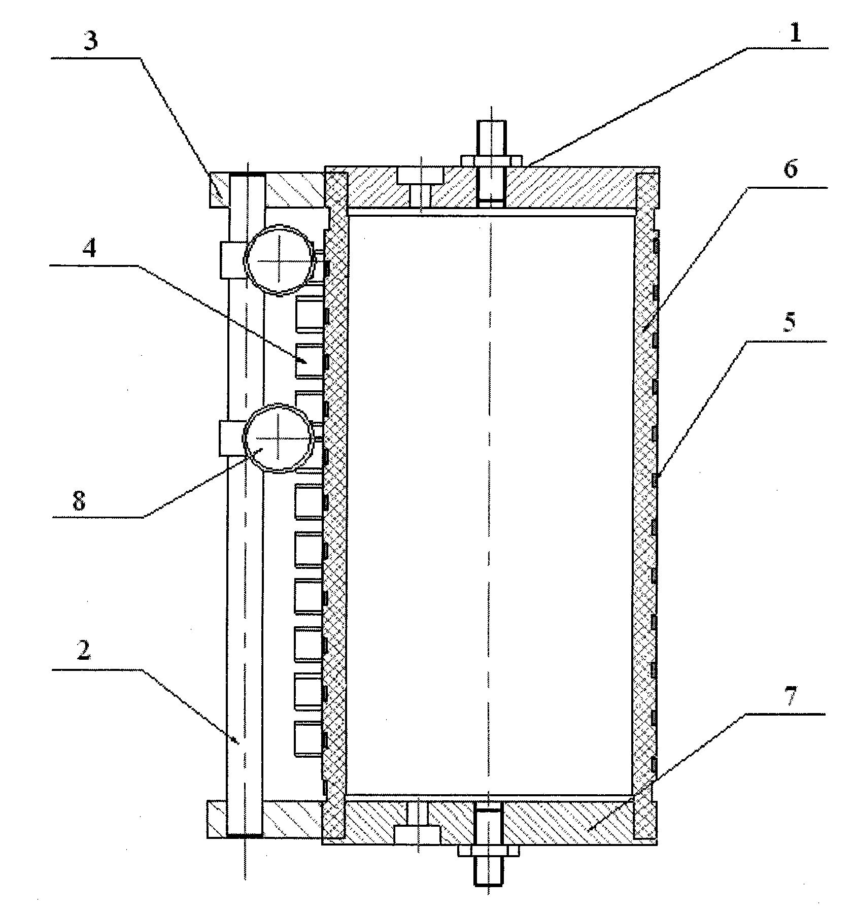
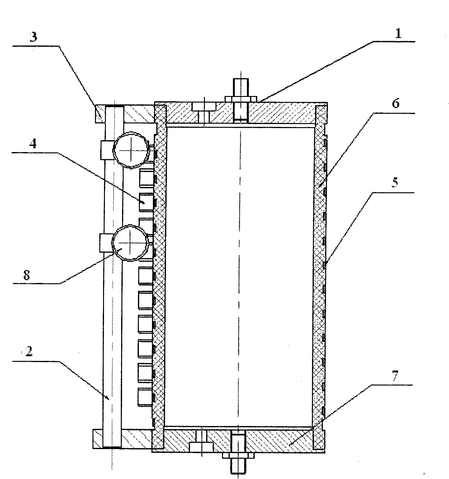
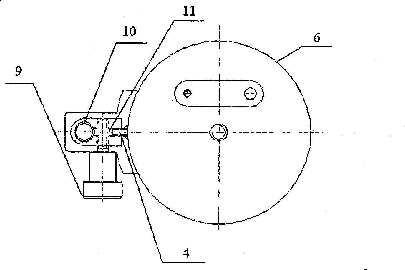
The invention relates to a lightening current waveform inductance which comprises an insulated barrel as well as an upper electrode and a lower electrode which are arranged on the insulated barrel. An electric inductive coil is wound around the insulated barrel; the outer side of the insulated barrel is respectively provided with two insulated brackets connected with the upper electrode and the lower electrode; a short-circuit rod is arranged on the two insulated brackets, and two moving slide blocks which can move up and down along the short-circuit conductive rod are arranged on the short-circuit conductive rod; and a connecting block corresponding to the moving slide blocks is arranged on each winding of the electric inductive coil of the outer side of the insulated barrel. The connecting block is arranged on each winding of the electric inductive coil, and the short-circuit rod and the moving slide blocks arranged on the insulated brackets on the upper electrode and the lower electrode can be adjusted to enable the lightening current waveform inductance to be conveniently adjusted so as to meet the needs of different test objects such as 10 / 350 mus, 8 / 20 mus lightning current tests, and the like. The invention has the advantages of large discharge current capacity, stable and reliable operation, and the like.
Description
Lightning current waveform forming inductance technical field The invention relates to an inductance element for adjusting a lightning current waveform, in particular to an inductance for forming a lightning current waveform. Background technique The 10 / 350μs and 8 / 20μs impulse current waves are the test waveforms of lightning arrester valves, low-voltage zinc oxide varistors, and surge protectors specified by IEC and national standards. It is a double-exponent generated by RLC circuit simulation. current wave. In the RLC current, the role of the inductor L is to adjust the waveform parameters of the lightning current waveform, thereby generating the lightning current wave specified by IEC and national standards, such as 10 / 350μs direct lightning current wave and 8 / 20μs lightning current wave. In order to meet the requirements of lightning current tests for different test objects (such as SPD, lightning discharge box, communication cabinet, communication station, etc.), t...
Claims
Login to View More Application Information
Patent Timeline
 Patent Type & Authority Patents(China)
IPC IPC(8): H01F21/02H01F29/00H01F27/28
Inventor 陈景亮姚学玲
Owner XI AN JIAOTONG UNIV
Features
- R&D
- Intellectual Property
- Life Sciences
- Materials
- Tech Scout
- Unparalleled Data Quality
- Higher Quality Content
- 60% Fewer Hallucinations
Learn More Browse by: Latest US Patents, China's latest patents, Technical Efficacy Thesaurus, Application Domain, Technology Topic, Popular Technical Reports.
© 2025 PatSnap. All rights reserved.Legal|Privacy policy|Modern Slavery Act Transparency Statement|Sitemap|About US| Contact US: help@patsnap.com