Control method, system and apparatus for far-end camera
A control method and technology of a control device, which are applied in the field of video conferencing, can solve the problems of complicated control of remote cameras, and achieve the effects of improving experience and intuitive and simple operation process.
- Summary
- Abstract
- Description
- Claims
- Application Information
AI Technical Summary
Problems solved by technology
Method used
Image

Examples
Embodiment 1
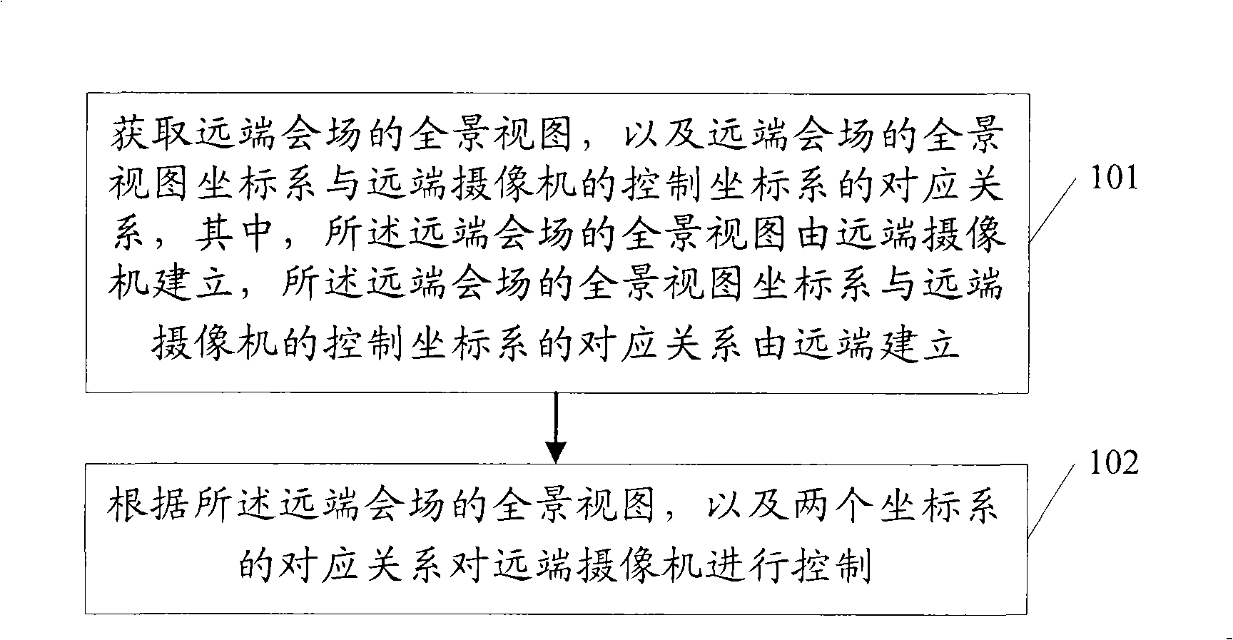
[0043] Method embodiment 1 of the present invention can be through figure 1 Be explained:
[0044] 101. Obtain the panoramic view of the remote conference site, and the corresponding relationship between the panoramic view coordinate system of the remote conference site and the control coordinate system of the remote camera, wherein the panoramic view of the remote conference site is established by the remote camera, and the remote The corresponding relationship between the panoramic view coordinate system of the end venue and the control coordinate system of the far-end camera is established by the far end;
[0045] In implementation 101, the panoramic view of the remote conference site is established by the remote camera, and the corresponding relationship between the panoramic view coordinate system of the remote conference site and the control coordinate system of the remote camera is established by the remote end, and they are all established through It is obtained from ...
Embodiment 2
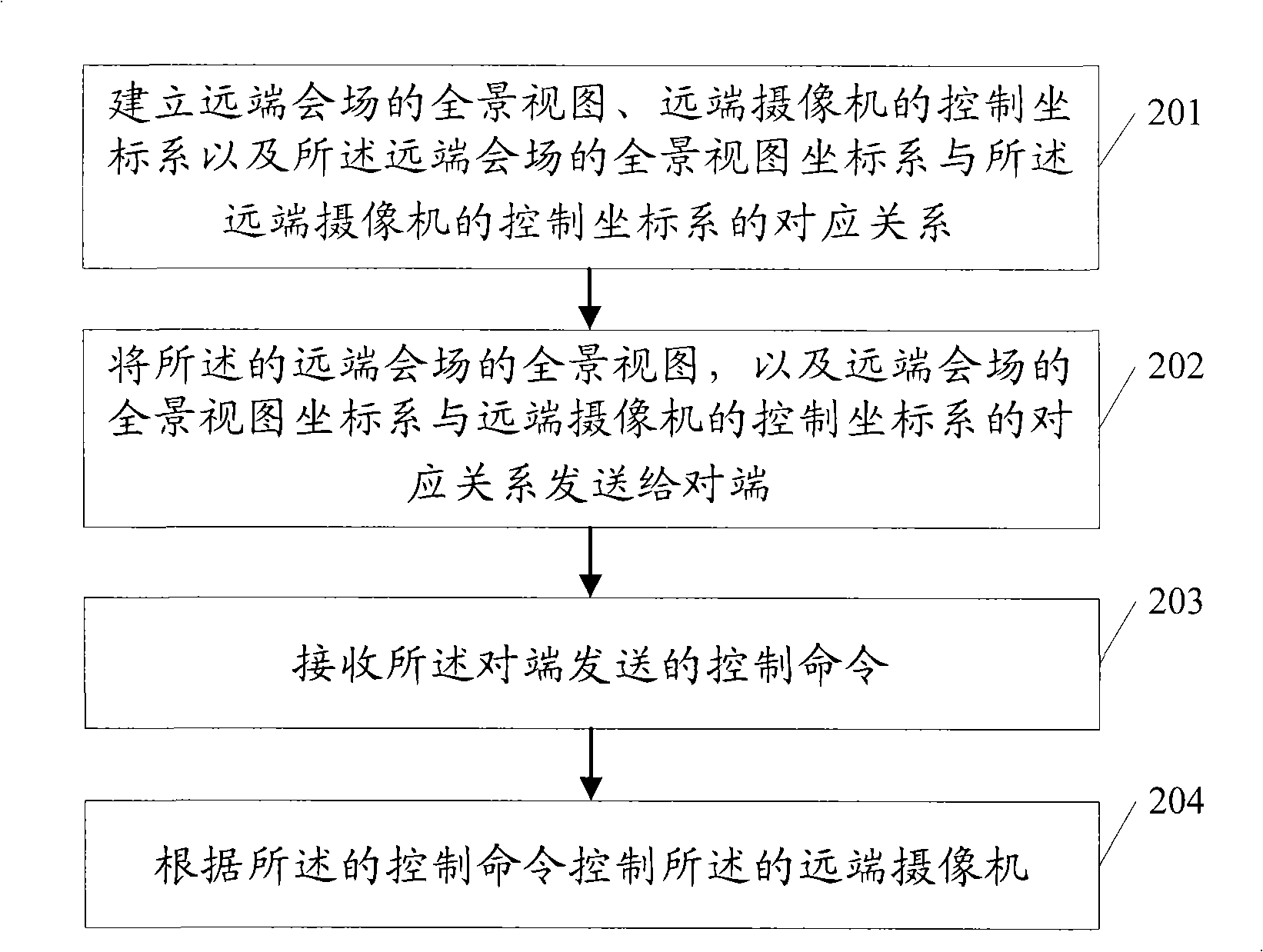
[0051] Method embodiment 2 of the present invention can pass figure 2 Be explained:
[0052] 201. Establish the control coordinate system of the remote camera, shoot the panoramic view of the remote conference site according to the control coordinate system of the remote camera, and establish the panoramic view coordinate system of the remote conference site and the control coordinates of the remote camera The corresponding relationship of the department;
[0053] When implementing 201, the process of establishing the control coordinate system of the far-end camera is specifically: setting the vertex of the upper left corner in the field of view of the far-end camera as the origin of the control coordinate system; The control coordinate system of the remote camera is established downward and inward along the paper.
[0054] The process of shooting the panoramic view of the far-end conference site according to the control coordinate system of the far-end camera is specifically...
Embodiment 3
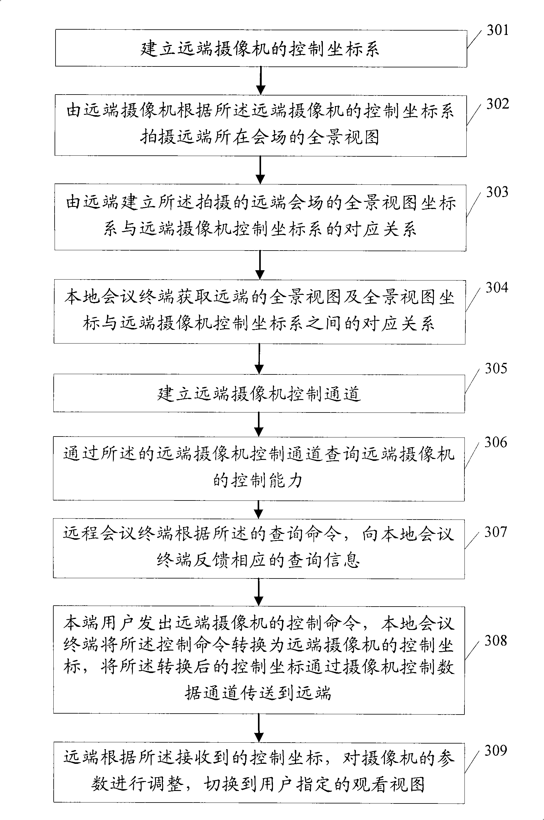
[0063] Method embodiment 3 of the present invention can be through image 3 Be explained:
[0064] 301. Establish a control coordinate system of the remote camera;
[0065] In implementation 301, the control coordinate system of the far-end camera includes three-dimensional components, namely (P, T, Z), and its specific structure is shown in Figure 4 As shown, the control coordinate system of the remote camera includes three coordinate axes, p, t, and z axes, where the origin is o, the origin of the p direction is selected at the far left, and the right is the direction of increase; the origin of the t direction Select at the top, and the downward direction is the direction of increase; the origin of the z direction is selected at the minimum zoom point of the camera (that is, the place where the field of view is the largest), and the direction of its enlargement is the direction of increase. The control coordinates of the remote camera can be realized in steps, for example...
PUM
 Abstract
Description
Claims
Application Information
 - R&D
- Intellectual Property
- Life Sciences
- Materials
- Tech Scout
- Unparalleled Data Quality
- Higher Quality Content
- 60% Fewer Hallucinations
Browse by: Latest US Patents, China's latest patents, Technical Efficacy Thesaurus, Application Domain, Technology Topic, Popular Technical Reports.
© 2025 PatSnap. All rights reserved.Legal|Privacy policy|Modern Slavery Act Transparency Statement|Sitemap|About US| Contact US: help@patsnap.com