
Non-contact clutch position sensor

A clutch position, non-contact technology, applied in the direction of using electric/magnetic devices to transmit sensing components, can solve problems such as poor contact and poor working reliability, achieve accurate and more stable output signals, prolong working life, and have broad application prospects. Effect

Active Publication Date: 2010-09-01
HEFEI BANGLI ELECTRONICS
View PDF0 Cites 0 Cited by
  • Summary
  • Abstract
  • Description
  • Claims
  • Application Information

AI Technical Summary

Problems solved by technology

[0004] In order to solve the problems of poor working reliability caused by poor contact in the contact clutch position sensor, the present invention provides a non-contact clutch position sensor

Method used


Image

  • Non-contact clutch position sensor
  • Non-contact clutch position sensor
  • Non-contact clutch position sensor

Examples


Embodiment

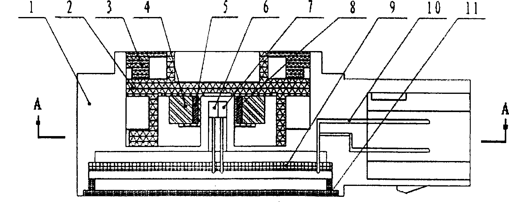
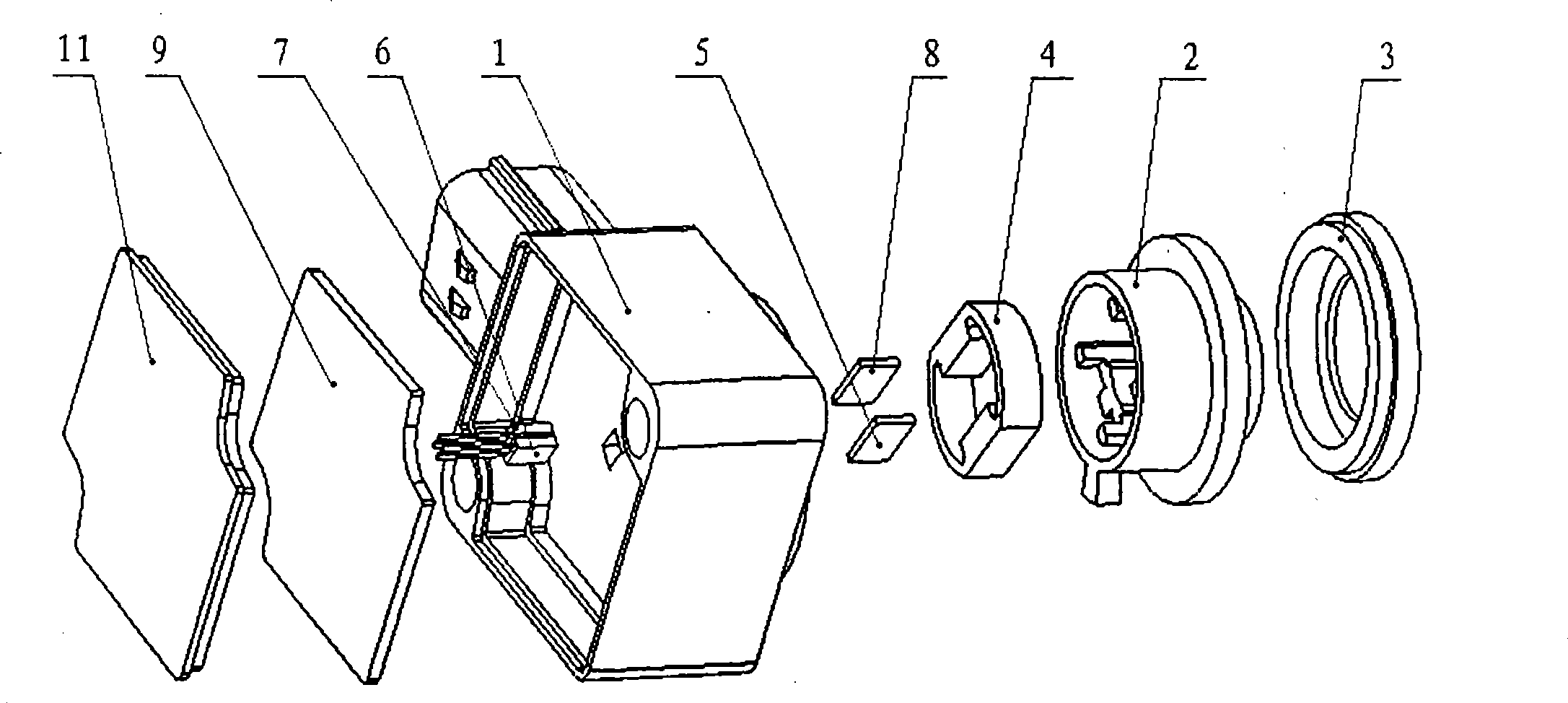
[0018] see figure 1 , figure 2 , the non-contact clutch position sensor includes a housing 1, an upper cover 3 and a rear cover 11, a rotor 2 and a circuit board 9 are installed in the housing 1, and the circuit board 9 corresponds to the inner side of the rear cover 11 and is connected to the circuit The terminal 10 connected to the board 9 extends out of the housing;

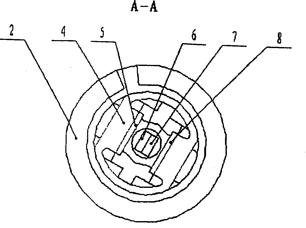
[0019] The rotor 2 is a cylindrical body with one end closed in the axial direction. A magnetic steel ring 4 is installed inside the rotor 2. The inner walls of the magnetic steel ring 4 are respectively symmetrically installed with A permanent magnet block 5 and B permanent magnet block 8, and A permanent magnet block 5 and B permanent magnet block. A cavity is formed between the permanent magnet blocks 8; the middle part of the circuit board 9 is respectively connected to the A Hall chip 6 and the B Hall chip 7 through two conductor rods, and the A Hall chip 6 and the B Hall chip 7 are located on the A per...


PUM


Abstract

The invention relates to a position sensor for a non-contact clutch, which solves the problems that the poor contact existing in the prior position sensor of the non-contact clutch leads to poor operational reliability and so on, The position sensor for the non-contact clutch comprises a shell, a rotor, a circuit board and so on, wherein a magnetic steel ring is arranged in the cylindrical rotor,the inner wall of the magnetic steel ring is symmetrically provided with two permanent magnet blocks respectively, and a cavity is formed between the two permanent magnet blocks; and the middle part of the circuit board is connected with an A Hall chip and a B Hall chip through two conducting member bars respectively, and the A Hall chip and the B Hall chip are positioned in the cavity between the two permanent magnet blocks. The sensor solves the problem of contact wear and prolongs service life; the sensor has good linear output characteristic and ensures that an output signal is more accurate and stable; the adopted Hall chips have functions of programmable property and temperature compensation, can flexibly change parameters of output voltage according to the requirement of customers,and automatically compensate and calibrate the magnetic field drift when the magnetic field intensity of a magnet drifts with the change of the temperature.

Description

technical field [0001] The invention relates to an automobile clutch position sensor. Background technique [0002] Electronic parking brake technology EBP (Electrical Brake Park) refers to a technology that integrates temporary braking during driving and long-term braking after parking, and realizes parking braking by electronic control. If emergency braking is required, the driver only needs to press the "EBP" button on the center console, and the vehicle will use the hydraulic action of ESP to generate the maximum braking force on the four wheels at the same time, allowing the car to stabilize within the shortest distance. Steady stop; at the same time, the system can automatically apply the brakes after the engine is turned off; it improves the safety performance of the vehicle, effectively prevents "slipping slopes", and ensures the safety of vehicles and personnel in both dynamic and static situations. [0003] The clutch position sensor is a device used to detect the...

Claims


Application Information

Patent Timeline
Patent Type & Authority Patents(China)
IPC IPC(8): G01D5/14
Inventor 周革张肖康汪长根
Owner HEFEI BANGLI ELECTRONICS
Learn More