Method, decoder and main control module for enlarging local region of image

A local area and image area technology, applied in the field of image processing, can solve the problems of image quality reduction, image resolution reduction, etc., and achieve the effect of avoiding the sacrifice of resolution

Active Publication Date: 2011-11-09
ZHEJIANG UNIVIEW TECH CO LTD
View PDF0 Cites 1 Cited by
  • Summary
  • Abstract
  • Description
  • Claims
  • Application Information

AI Technical Summary

Problems solved by technology

Since the high-definition camera inputs the digital image with high-definition resolution to the FPGA, and the FPGA must convert the digital-analog image with high-definition resolution into a BT656 signal based on the D1 format before transmitting it to the DSP. After this conversion, the resolution of the image is reduced. , resulting in reduced image quality

Method used


Image

  • Method, decoder and main control module for enlarging local region of image
  • Method, decoder and main control module for enlarging local region of image
  • Method, decoder and main control module for enlarging local region of image

Examples


Embodiment Construction
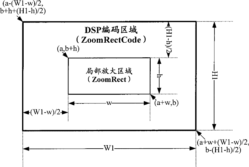
[0042] The core idea of ​​the present invention is: the decoder notifies the encoder of the location information of the local magnified area, and the encoder only encodes the preset encoding area centered on the local magnified area, thereby improving The resolution of the partially enlarged area is improved. Wherein, the resolution of the preset encoding area is less than the resolution of the camera and greater than or equal to the resolution of the encoded output image.

[0043] The present invention will be further described in detail below in conjunction with the drawings and specific embodiments.

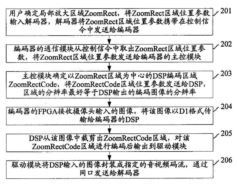
[0044] figure 2 This is a flowchart of zooming in a local area of ​​an image collected by a camera according to the first embodiment of the present invention, such as figure 2 As shown, the specific steps are as follows:

[0045] Step 201: The user determines the local zoom area ZoomRect, inputs the position parameter of the ZoomRect area into the decoder, and the decoder carries ...


PUM


Abstract

The invention discloses a method, an encoder and a main control module for magnifying the partial area of an image. The method comprises the following steps: a partial enlarging area is set in advance; the encoder cuts out an encoding area which takes the partial enlarging area as the center and has the distinguishability to be equal to a predetermined encoding distinguishability from images collected by a camera according to the received position information of the appointed partial enlarging area; and the encoder encodes the encoding area and then sends the encoded area to a decoder. The invention achieves the purpose of improving the distinguishability of the partial area after being magnified while magnifying the partial area under the condition that a camera with a tripod head is notneeded.

Description

Technical field [0001] The invention relates to the technical field of image processing, in particular to a method, an encoder and a main control module for enlarging a local area of ​​an image. Background technique [0002] With the development of video and audio codec technology and network storage technology, digital video surveillance technology is formed by digitizing the image data collected by cameras and transmitting and storing them on the Internet. [0003] Video surveillance technology is a key technology in urban security systems. After recent years of development, video surveillance technology has formed an integrated surveillance mode of "analog surveillance + network surveillance storage + comprehensive management". The video surveillance system is mainly composed of analog surveillance camera devices, hardware encoders, hardware decoders, network storage equipment and management systems. In current video surveillance systems, the storage of surveillance image data...

Claims


Application Information

Patent Timeline
Patent Type & Authority Patents(China)
IPC IPC(8): H04N7/26H04N19/34
Inventor 苏佳周迪
Owner ZHEJIANG UNIVIEW TECH CO LTD
Why Eureka
Try Eureka