Anti-oil leakage device of top bend needle mechanism

A looper and oil leakage technology, which is applied in safety devices, engine lubrication, lubrication/cooling devices, etc., can solve the problems of not being able to maintain the oil leakage prevention function and oil leakage in a long-term and stable manner, and achieve reliable stability , the effect of less wear

Inactive Publication Date: 2012-03-21
YAMATO SEWING MASCH MFG CO LTD
View PDF3 Cites 0 Cited by
  • Summary
  • Abstract
  • Description
  • Claims
  • Application Information

AI Technical Summary

Problems solved by technology

[0007] However, as a result of further research on the patented technology proposed by the present applicant, it was found that there is still a problem that a part of the remaining lubricating oil scraped off by the elastic lip 21a of the oil seal ring 21 goes back to the The outer peripheral portion of the oil seal ring 21 is accumulated in the small space x formed between the oil seal ring 21 and the end inner peripheral surface of the through long hole 19, and the lubricating oil accumulated in the small space x is moved along with the upper looper guide. The reciprocating rotation of 6 splashes to the top of the oil seal ring 21, and the splashed lubricating oil adheres to the outer peripheral surface of the upper looper table 8 again, and scatters upward to the outside, which will cause oil leakage in a short period of use.
This oil leakage occurs in a shorter period of time when the amount of oil supplied to the outer peripheral surface of the upward looper table 8 increases, and there is a problem that the predetermined oil leakage prevention function cannot be maintained stably for a long period of time.

Method used


Image

  • Anti-oil leakage device of top bend needle mechanism
  • Anti-oil leakage device of top bend needle mechanism
  • Anti-oil leakage device of top bend needle mechanism

Examples


Embodiment Construction

[0035] Hereinafter, embodiments of the present invention will be described with reference to the drawings.

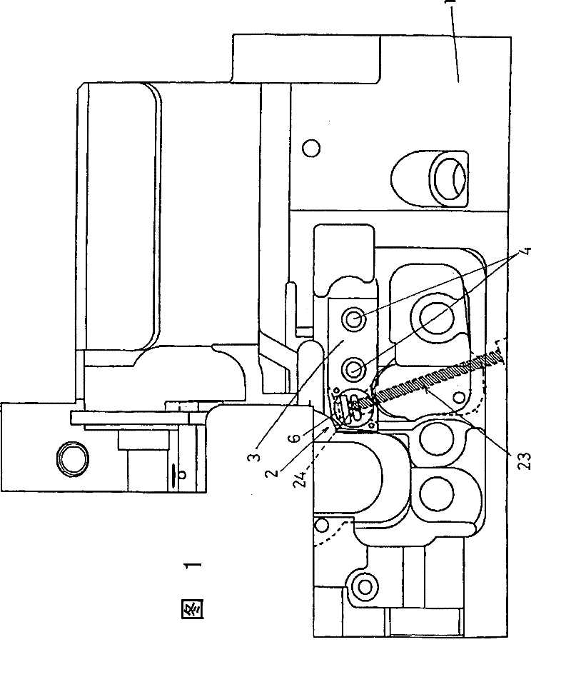
[0036] figure 1 To show the entire sewing machine frame 1 in the overlock sewing machine equipped with the oil leakage prevention device of the upper looper mechanism of the first embodiment of the present invention in a state where the front cover (not shown) installed on the sewing machine frame 1 is removed The front view of the sewing machine frame 1 reveals the upper looper mechanism 2.

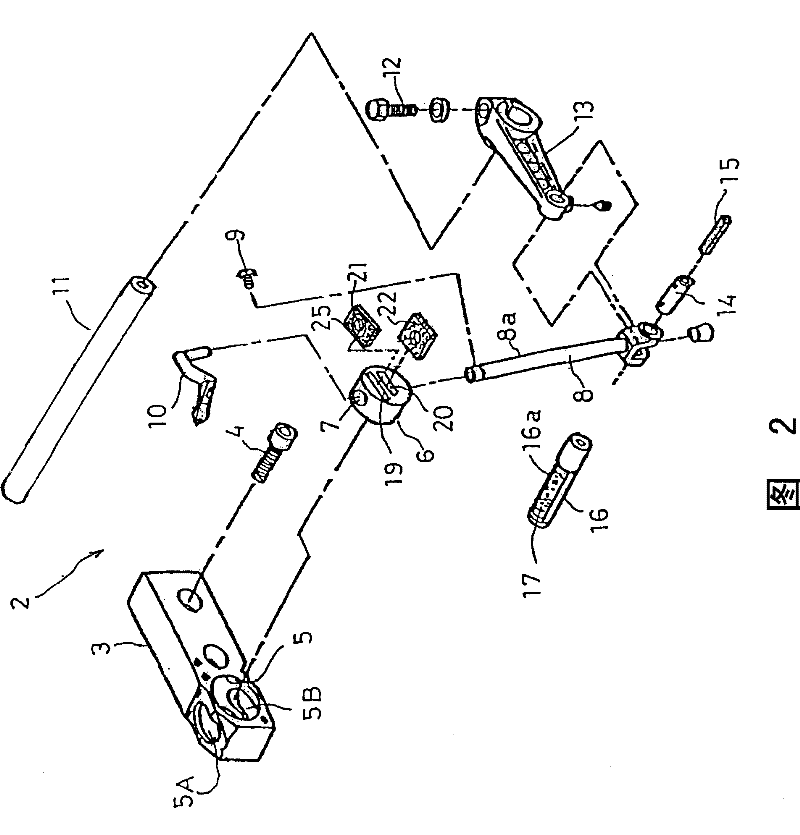
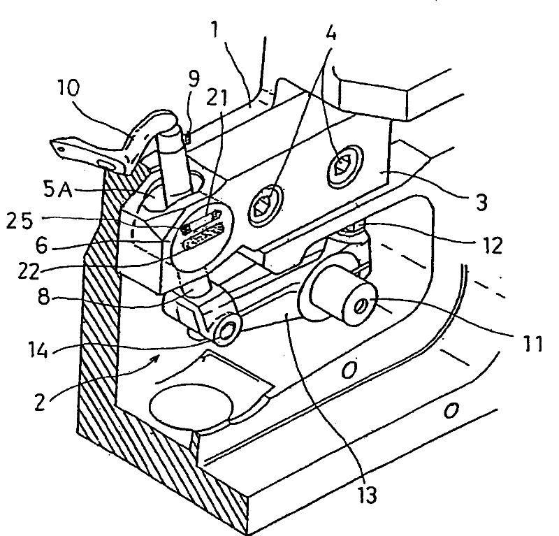
[0037] figure 2 Is an exploded perspective view of the upper looper mechanism 2, image 3 Is an assembly perspective view of the upper looper mechanism 2, Figure 4 This is the front view of the upper looper mechanism 2. In these figures, the symbol 3 is an upper looper guide member fixed to the front of the sewing machine frame 1 by a fixing screw 4. A circular hole 5 along the cloth feeding direction is formed at the front end of the upper looper guide member 3. The shaped hole 5 ...


PUM


Abstract

The invention relates to an oil leak preventing device for an upwards curved needle mechanism. A columned upwards curved needle guiding body capable of being freely and rotationally inserted and kept on a circular hole formed on an upwards curved needle guiding component is formed with an upper communicating slotted hole and a lower communicating slotted hole orthogonal with a communicating hole for sliding and lifting of an upwards curved needle table, an oil seal ring elastically and glidingly contacting the outer peripheral face of the upwards curved needle table and provided with a labialpart for scraping lubricating oil is inserted in the upper communicating slotted hole, and an oil suction ring capable of sucking and keeping the scraped residual lubricating oil is inserted in the lower communicating slotted hole, therefore, the oil leak preventing device can reliably and favorably exert scraping function of the residual lubricating oil, can reliably prevent the scraped residuallubricating oil from being attached to the outer peripheral face of the upwards curved needle table again to disperse upwards, and can stably maintain the oil link preventing function for a long term.

Description

Technical field [0001] The invention relates to an oil leakage prevention device for an upper looper mechanism in an overlock sewing machine, in particular to an overlock sewing machine, in order to improve the high-speed operation performance of the sewing machine, and prevent the remaining lubricating oil in the lubricating oil supplied to the outer peripheral surface of the upward looper The sliding movement of the table is an oil leakage prevention device for the upper looper mechanism that leaks to the surroundings, especially the upper portion of the upward looper guide member, and soils threads and fabrics. More specifically, it relates to an oil leakage prevention device for an upper looper mechanism having the following basic structure, which includes: an upper looper guide member fixed to a frame of a sewing machine; and a circular hole formed in the upper looper guide member The cylindrical upper looper guide body is fitted and held in a form that can rotate freely ar...

Claims


Application Information

Patent Timeline
Patent Type & Authority Patents(China)
IPC IPC(8): D05B71/02D05B57/06
CPCD05B57/06D05B71/02D05D2205/32F16N7/00F16N29/00F16N2210/32F16N2260/00
Inventor 金川靖男
Owner YAMATO SEWING MASCH MFG CO LTD
Why Eureka
Try Eureka