Device for self-arranging and bonding battery

An automatic arrangement and battery technology, which is applied in the direction of secondary batteries, battery components, primary batteries to battery groups, etc., can solve the problems of low production efficiency and high error rate, and achieve the effect of improving production efficiency and eliminating arrangement errors

Active Publication Date: 2009-03-04
OPTIMUM BATTERY CO LTD
View PDF0 Cites 7 Cited by
  • Summary
  • Abstract
  • Description
  • Claims
  • Application Information

AI Technical Summary

Problems solved by technology

The current production process is to manually arrange the batteries, turn over the adjacent batteries, and then manually dispense glue. The disadvantages of this method are: low production efficiency and high error rate

Method used


Image

  • Device for self-arranging and bonding battery
  • Device for self-arranging and bonding battery
  • Device for self-arranging and bonding battery

Examples


Embodiment 1

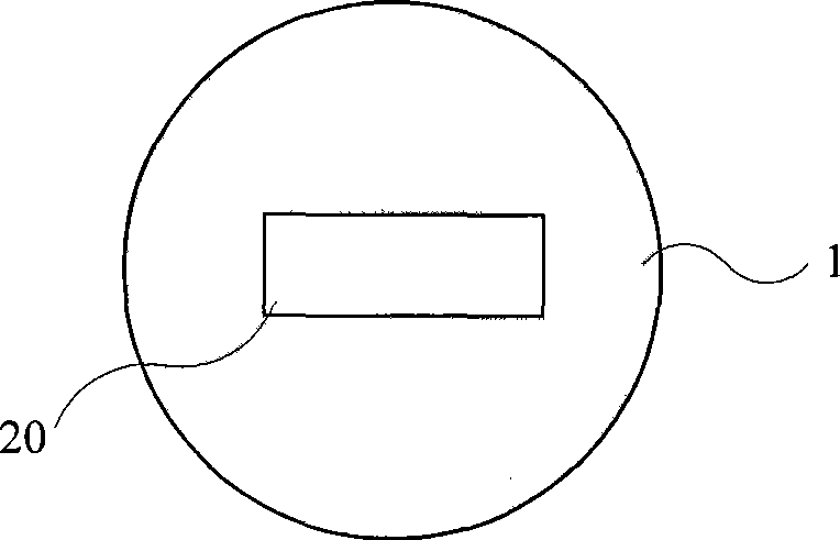
[0016] like figure 1 , figure 2 As shown, the AAA type batteries 8 to be packaged are placed in the battery slot 7, when placed, the positive poles of all the batteries 8 are all facing the same direction, and of course, the negative poles of all the batteries 8 are also all facing the same direction. The side of battery tank 7 horizontal section by battery 8 entrance has a push block 4, and push block 4 links to each other with cylinder 5, and cylinder 5 drives push block 4 to do reciprocating motion. There is a belt conveyor 6 at the bottom of the tank near the battery tank 7 horizontal section of the push block 4. The middle part of the horizontal section of the battery tank 7 is disconnected, and a rotating disk 1 is located therebetween. Battery dispensing is realized by a glue dispenser 3 , which includes a glue bottle 31 , a glue delivery tube 32 , a peristaltic pump 33 , an air cylinder 34 and a glue dispensing head 35 .

[0017] like image 3 As shown, the rotati...

Embodiment 2

[0023] like Figure 5 , Figure 6 As shown, the AA-type batteries 18 to be packed are placed in the battery slot 17. When placed, the positive poles of all the batteries 18 are all facing the same direction, and of course, the negative poles of all the batteries 18 are also all facing the same direction. The battery tank 17 horizontal section has a push block 15 by the side of the battery 18 inlet, and the push block 15 links to each other with the cylinder 16, and the cylinder 16 drives the push block 15 to reciprocate. There is a belt conveyor 19 at the bottom of the tank near the battery tank 17 horizontal sections of the push block 15. The middle part of the horizontal section of the battery groove 17 is disconnected at two places, and the rotating disk 9 and the rotating disk 12 are respectively located therebetween. The battery groove is connected between the rotating disk 9 and the rotating disk 12, and the length of the battery groove is equal to the width of an AA ba...


PUM


Abstract

The invention relates to a device for the automatic arrangement and bonding of batteries, which belongs to the technical field of battery packing equipment and consists of a battery cell (7), a pushing block (4), a rotating disc (1) and a glue applier (3); wherein, a battery (8) is placed in the battery cell (7), the pushing block (4) makes reciprocating movement periodically along the extending direction of the battery cell (7) so as to push the battery (8) to move forward and set the displacement of the size of the diameter of a plurality of batteries; in the interval when the pushing block (4) pushes the battery forward by two times, the rotating disc (1) rotates by half cycle so as to drive the battery in the rotating disc to turn by half cycle; the glue applier (3) carries out dispensing to the batteries which are turned and arranged and the frequencies of the reciprocating movement of the pushing block (4), the half-cycle type rotation of the rotating disc (1) and the dispensing movement of the glue applier (3) are same. The device replaces the traditional manual arrangement and dispensing method, improves the production efficiency greatly and simultaneously avoids occurrence of the situation of wrong arrangement.

Description

technical field [0001] The invention relates to the technical field of battery manufacturing, and more specifically, relates to a device for battery packaging. Background technique [0002] Batteries are a very convenient means of power supply, especially for rechargeable batteries, which have been widely used in electric toys, electric tools and other fields because of their advantages of being reusable many times. However, the voltage and power of a single battery are very limited. In actual use, usually a number of single batteries are combined in series and in parallel and bonded together to form a battery pack. [0003] When packing a single battery into a battery pack, in order to save space, the batteries are often arranged side by side. In this case, if you want to connect the batteries in series, the best way is to make every two adjacent batteries upside down. Connect to the adjacent positive and negative poles. The current production process is to manually arran...

Claims


Application Information

Patent Timeline
IPC IPC(8): H01M6/42H01M10/00H01M2/10B65D85/88H01M50/20
Inventor 李瑶
Owner OPTIMUM BATTERY CO LTD
Why Eureka
Try Eureka