
Image forming apparatus and image forming method

An imaging device and imaging unit technology, which is applied in the fields of electric recording process equipment, electric recording technology, optics, etc. that apply charge patterns, can solve problems such as uneven concentration, reduce the difference in concentration uniformity, and reduce consumption volume effect

Inactive Publication Date: 2009-02-11
FUJIFILM BUSINESS INNOVATION CORP
View PDF2 Cites 8 Cited by
  • Summary
  • Abstract
  • Description
  • Claims
  • Application Information

AI Technical Summary

Problems solved by technology

[0002] In an image forming apparatus employing an intermediate transfer system that primarily transfers a toner image from a photoconductor drum to an intermediate transfer belt, sometimes the Density unevenness occurs in the direction of rotation of the drum

Method used


Image

  • Image forming apparatus and image forming method
  • Image forming apparatus and image forming method
  • Image forming apparatus and image forming method

Examples


Embodiment Construction

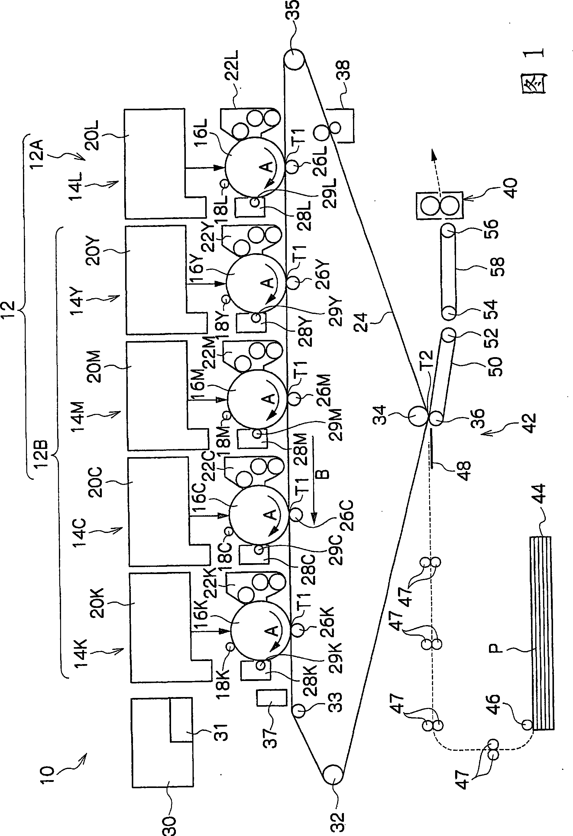
[0071] Hereinafter, the manner of carrying out the present invention will be described in detail based on the exemplary embodiments shown in the drawings. It is to be noted that the recording paper P will be described as an example of the recording medium. In addition, a transparent toner (hereinafter referred to as "clear toner") Lt will be described as an example of a base toner. The clear toner Lt is a toner that becomes transparent after it is fixed on the recording paper P by a fixing device 40 described later, and the clear toner Lt is less likely to affect color change than color toners. In addition, common parts between the respective colors are explained by adding letters corresponding to the respective colors to the end of the reference numerals.

[0072] In the present invention, "basic toner" refers to white, transparent or milky white toner, and "color toner" refers to toners including colors (such as yellow, magenta, cyan and black that are often used in imaging...


PUM


Abstract

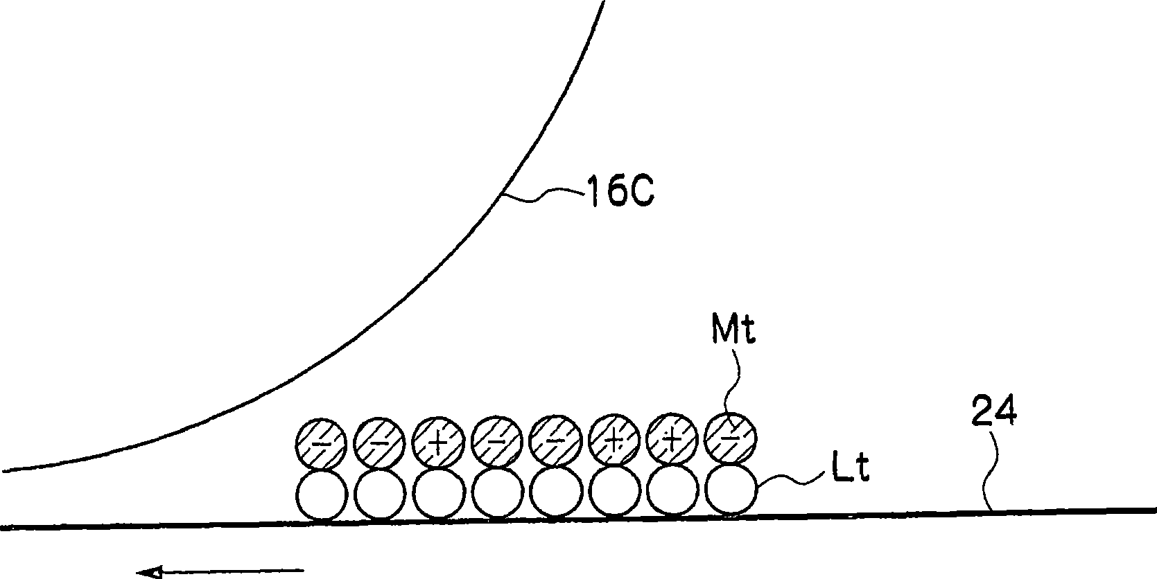
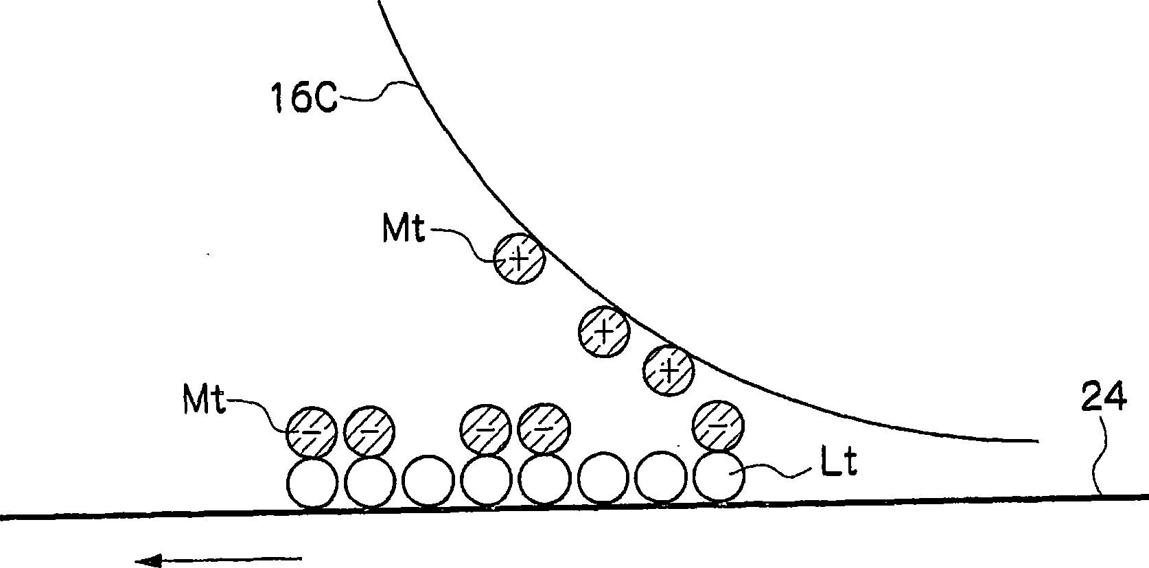
The present invention provides an image forming apparatus and an image forming method, which are capable of reducing density unevenness difference between single color and multicolor. The image forming apparatus comprises a first image forming unit that transfers a base toner image formed on a first image carrier to an intermediate transfer member and forms an image and second image forming units that are plurally disposed downstream of the first image forming unit in a moving direction of the intermediate transfer member, transfer different color toner images formed on second image carriers to the intermediate transfer member and form images. The base toner image is formed beforehand in a single color region transferred onto the intermediate transfer member from the second image carriers of the second image forming units.

Description

technical field [0001] The present invention relates to an imaging device and an imaging method. Background technique [0002] In an image forming apparatus employing an intermediate transfer system that primarily transfers a toner image from a photoconductor drum to an intermediate transfer belt, sometimes the Density unevenness occurs upward on the rotational axis of the drum. As a means of correcting such density unevenness, a technique of minimizing a difference in density having a plurality of levels in the rotational axis direction of the photoconductor drum has conventionally been disclosed (see, for example, Japanese Patent Application Publication (JP-A) No. .2001-66835). Contents of the invention [0003] The present invention provides an image forming apparatus and an image forming method that can reduce the difference in density uniformity between monochrome and multicolor. [0004] A first aspect of the invention according to claim 1 of the present invention...

Claims


Application Information

Patent Timeline
Patent Type & Authority Applications(China)
IPC IPC(8): G03G15/16G03G15/01G03G15/00G03G13/16G03G13/01G03G13/00
CPCG03G15/0131G03G15/5058G03G2215/00059G03G2215/0129
Inventor 吉冈智章百武信男福原琢
Owner FUJIFILM BUSINESS INNOVATION CORP
Learn More