Method for supporting a weft guide element

A technology of yarn guides and conductive elements, applied in textiles and papermaking, looms, textiles, etc., can solve problems such as weakening performance and fabric quality

Inactive Publication Date: 2008-12-24
SULTEX AG
View PDF0 Cites 8 Cited by
  • Summary
  • Abstract
  • Description
  • Claims
  • Application Information

AI Technical Summary

Problems solved by technology

However, in the case of systems with weft thread guide elements, performance and fabric quality are often impaired by friction between the weft thread guide element and the support element or the lower shed warp threads

Method used


Image

  • Method for supporting a weft guide element
  • Method for supporting a weft guide element
  • Method for supporting a weft guide element

Examples


Embodiment Construction

[0042] Figure 1 shows the weft thread guide area of ​​a loom 10 with a guide groove 11 for a weft thread guide element 12 which is not shown more explicitly in Figure 1 , but which can in particular be obtained from figure 2 see. The loom 10 is double-sided weft insertion and is therefore equipped with acceleration devices 13, 13', weft selectors 14, 14' and braking devices 15, 15' on both sides of the guide groove 11. The guide channel 11 is located completely below the shed, not shown here. Furthermore, pre-charge chambers 29 , 29 ′ for the acceleration means 13 , 13 ′ can be seen, the function of which will be described in detail below with reference to FIG. 3 .

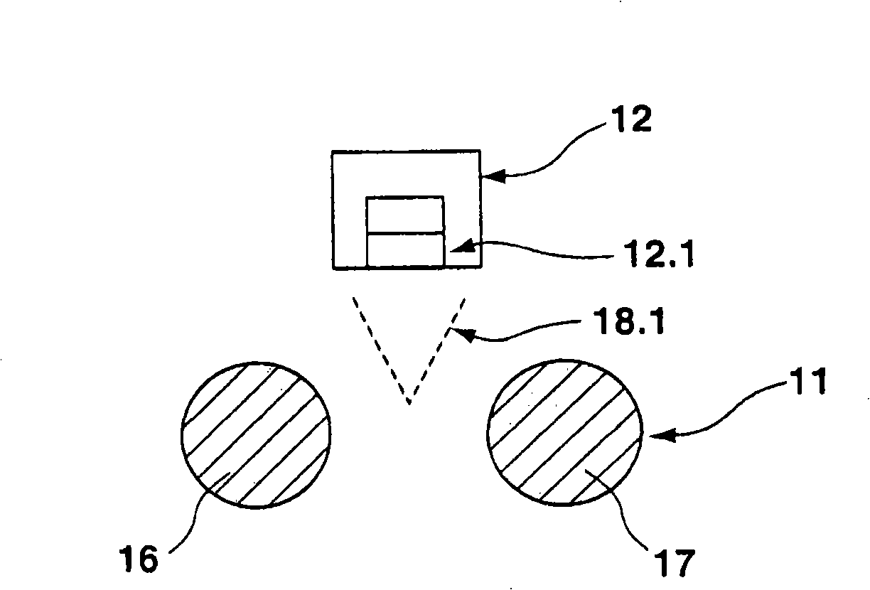
[0043] figure 2 The structure of the guide channel 11 of the weaving machine 10 in FIG. 1 is shown and thus its function is shown more clearly. A channel 11 is formed by two parallel bars 16 , 17 between which said channel 11 encloses a space 18 with an approximately V-shaped cross-section. The weft thread gui...


PUM


Abstract

The invention relates to a method for supporting a weft thread guiding element (12) in the shed of a loom, whereby a weft thread guiding element (12) is displaced in relation to at least one guide channel (11) and is thereby magnetically guided.

Description

Background technique [0001] Looms are classified into several types according to the way the weft yarns are inserted. [0002] In the case of a shuttle loom, the weft thread is passed through the shed under the action of a weft thread guide element on which the weft thread is wound. [0003] As far as shuttleless looms are concerned, a distinction is made between projectile weft insertion looms, rapier looms, air-jet looms and water-jet looms. In the last-mentioned weaving machine type, the weft thread is conveyed through the shed by means of air jets and water jets, respectively. These types of looms do not require support elements extending into the shed, but these looms do not have weft thread guide elements, which is why these looms cannot handle all types of yarns. Particularly smooth or heavy yarns are difficult to handle. [0004] Other types of looms are operated by weft thread guide elements, that is by projectiles, rapiers or shuttles. For weft thread insertion, ...

Claims


Application Information

Patent Timeline
Patent Type & Authority Applications(China)
IPC IPC(8): D03D47/27D03D47/24D03D47/38D03D49/42
CPCD03D47/24D03D47/277D03D49/42D03D49/44
Inventor M·法尔纳A·西梅昂
Owner SULTEX AG
Why Eureka
Try Eureka