
Crank mechanism in particular for a weighing sensor on a balance working on the electromagnetic force compensation principle

A technology of weighing sensor and lever transmission, which is applied in the field of lever transmission device of the weighing sensor of the scale working according to the principle of electromagnetic force compensation, which can solve the problems of high spring constant, poor rigidity, adverse effects on measurement accuracy, etc., Achieve high transmission ratio

Active Publication Date: 2008-10-01
WIPOTEC WIEGE UND POSITIONIERSYSTEME GMBH
View PDF4 Cites 5 Cited by
  • Summary
  • Abstract
  • Description
  • Claims
  • Application Information

AI Technical Summary

Problems solved by technology

On the other hand, however, this leads to a high resistance against the lever about the desired axis of rotation, i.e. the elastically deformable hinge has a high spring constant relative to the rotation about the desired axis of rotation, so that for this reason no transmission of any size can be realized with a single lever Compare
[0008] Furthermore, the known construction has the disadvantage that the elastically deformable hinge forming the lever's pendulum axis is less rigid both in the direction of translation perpendicular to the plane of longitudinal extension of the hinge and in the direction of rotation about an axis parallel to the direction of longitudinal extension of the hinge
When undesired static or dynamic forces occur (caused by undesired accelerations such as vibrations), this causes the measurement accuracy to be adversely affected

Method used


Image

  • Crank mechanism in particular for a weighing sensor on a balance working on the electromagnetic force compensation principle
  • Crank mechanism in particular for a weighing sensor on a balance working on the electromagnetic force compensation principle
  • Crank mechanism in particular for a weighing sensor on a balance working on the electromagnetic force compensation principle

Examples


Embodiment Construction

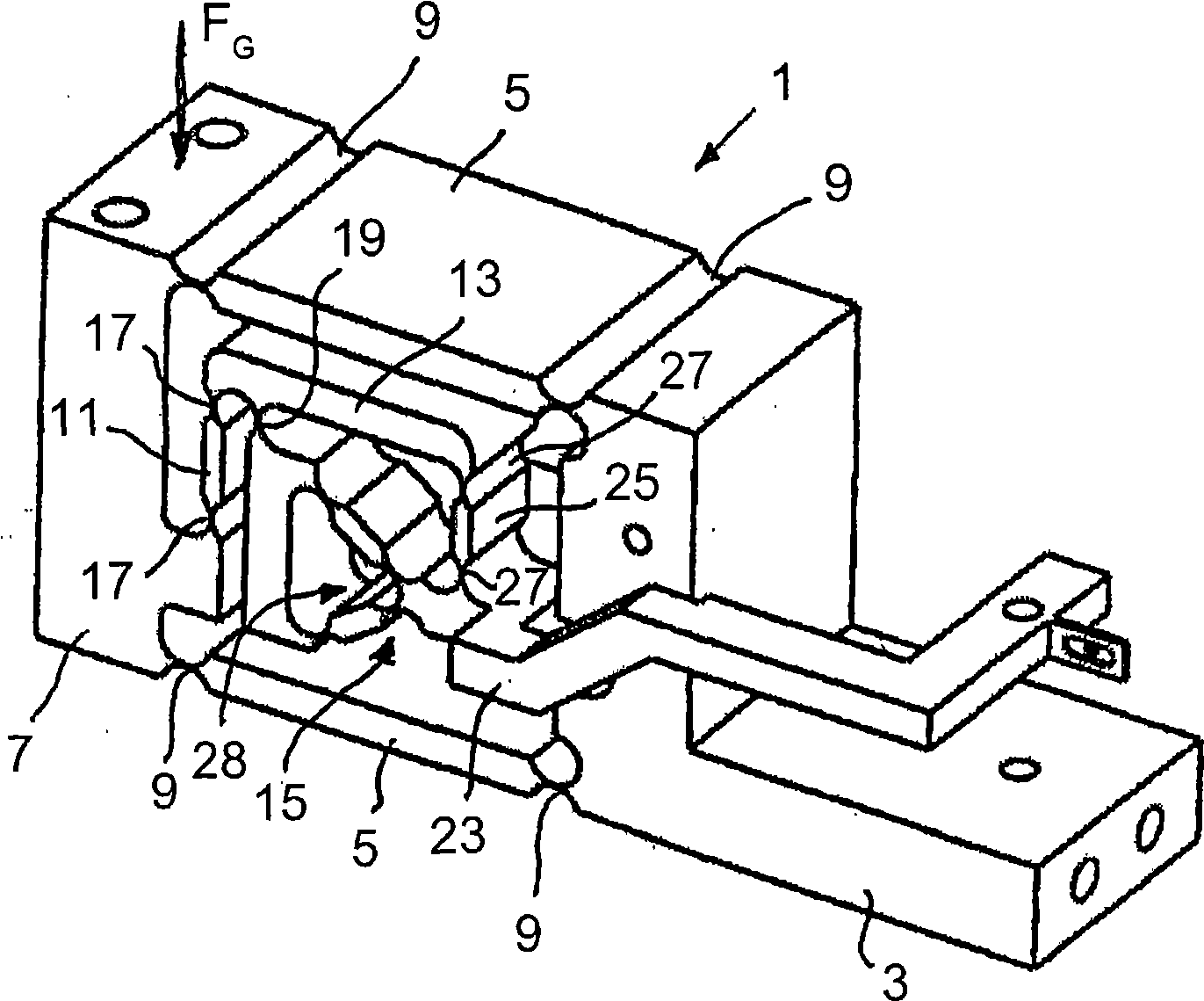
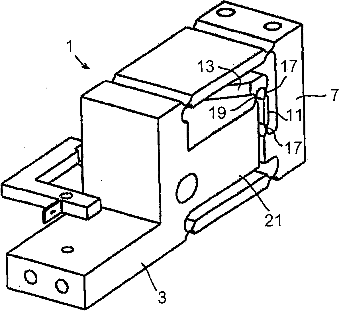
[0041] figure 1 The load cell 1 shown is of one-piece construction. In this embodiment, it is produced, for example, by machining a block of material, in particular milling and drilling. The load cell 1 comprises a body 3 which can be fixedly mounted, for example, in a housing of a scale. The main body 3 is connected to the carrier 7 via two parallel arms or parallel rods 5 , wherein the arms 5 are respectively connected to the stationary main body 3 and the carrier 7 by means of elastically deformable hinges 9 . The carrier 7 can be connected to a receiving device for items to be weighed (not shown).

[0042] The gravitational force FG acting on the carrier 7 causes a deflection of the parallel bars 5 and a movement of the carrier 7 towards the direction of gravity.

[0043] The carrier part 7 is connected via a connecting part 11 to the short lever arm of a first lever 13 of a two-stage lever transmission 15 . This connection in turn takes place via an elastically deform...


PUM


Abstract

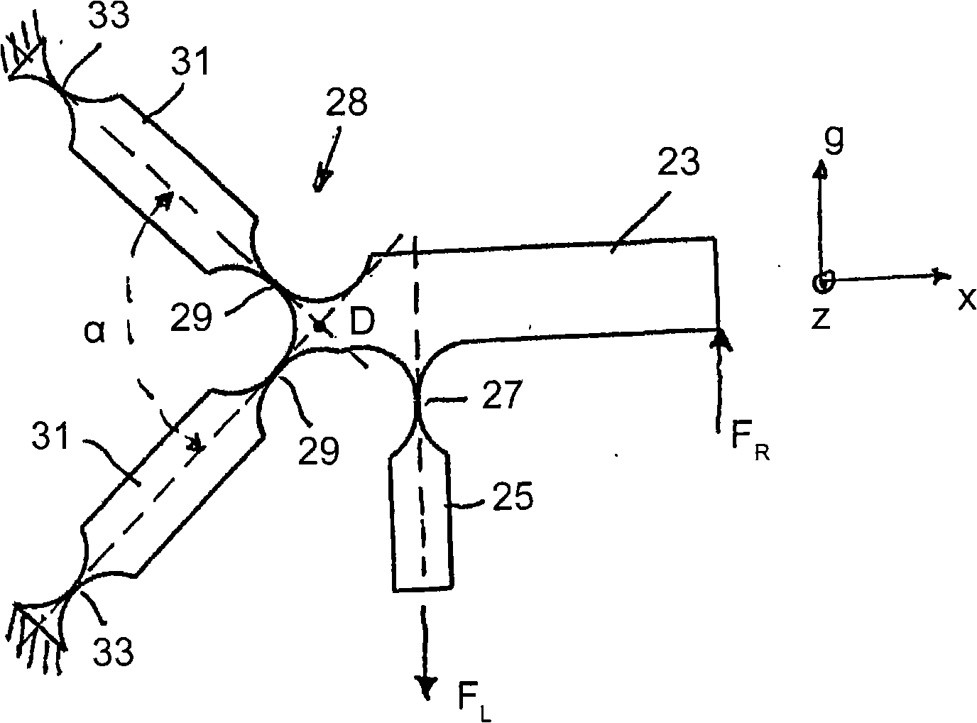
The invention relates to a crank mechanism, in particular, for a weighing sensor on a balance working on the electromagnetic force compensation principle, comprising at least one crank (23) connected to a fixed base body (3) or an element connected thereto, the at least one crank arm being connected to the base body (3) or the element connected thereto by means of an elastically-deformable joint (28), defining a pivot axis of the at least one crank (23) and a load force (FL) corresponding to the weight force (FG) or a derivative thereof acts on a first crank arm of the at least one crank which generates a reaction force (FR) on a second crank arm of the at least one crank.; According to the invention, the elastically-deformable joint (28) comprises two thin elastically-deformable flexible regions (29), connecting the crank directly or indirectly to the base body (3) or the element connected thereto, each flexible region (29) being flexible in a direction perpendicular to a longitudinally extending plane defined by the geometry of the flexible region (29) to generate a pivot movement of the at least one crank (23), the longitudinally-extending planes of the flexible regions (29) including an angle (a) which is not zero and a virtual pivot axis (D) for the at least one crank (29) is defined by the two elastically-deformable flexible regions (29).

Description

technical field [0001] The invention relates to a lever drive according to the features of the preamble of claim 1 , in particular for a load cell of a balance operating on the principle of electromagnetic force compensation. Background technique [0002] Various embodiments of lever drives and balances operating according to the principle of electromagnetic force compensation and suitable load cells are known. In order to obtain a sufficiently accurate weighing signal, an integrated load cell is mostly used, which has the advantage of high enough long-term stability compared with a non-integrated load cell. Currently, leading scale manufacturers no longer manufacture structures consisting of multiple parts such as wire springs, such as disclosed in DE 100 13 311 A1, which may be considered "obsolete technology". [0003] One-piece load cells can be manufactured in different ways, especially by milling or etching. DE 199 23 207 C1, for example, describes a complex three-di...

Claims


Application Information

Patent Timeline
Patent Type & Authority Applications(China)
IPC IPC(8): G01G21/24
CPCG01G21/244Y10T74/20582G01G21/166G01G21/07
Inventor 蒂莫·豪克
Owner WIPOTEC WIEGE UND POSITIONIERSYSTEME GMBH
Learn More