
Cover tape and method for manufacture

A technology for cover tapes and products, applied in the field of tapes carrying components, can solve the problems of poor stability of HAA cover tapes, reduced peeling force, and insufficient peeling force.

Active Publication Date: 2008-09-24
3M INNOVATIVE PROPERTIES CO
View PDF1 Cites 8 Cited by
  • Summary
  • Abstract
  • Description
  • Claims
  • Application Information

AI Technical Summary

Problems solved by technology

Even though cover tapes are advertised for use with different types of carrier tapes, they may still have suboptimal peel force and uneven peel
In addition, HAA cover tapes are less stable as peel force decreases over time and temperature

Method used


Image

  • Cover tape and method for manufacture
  • Cover tape and method for manufacture
  • Cover tape and method for manufacture

Examples


Embodiment Construction

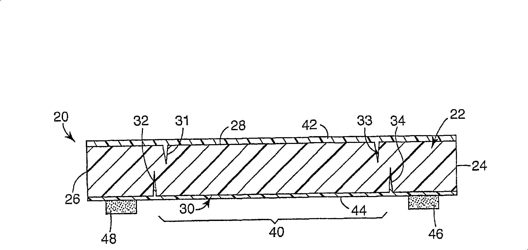
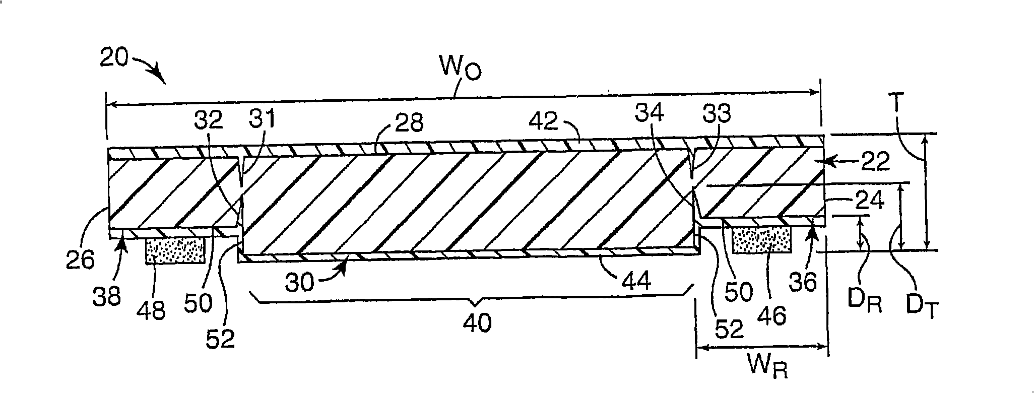
[0019] Aspects of the invention relate to cover tapes, carrier tape / cover tape systems, and methods of making cover tapes. The cover tape of the present invention can be adhered to a carrier tape which can hold components for storage and transport. The cover tape can cover pockets on the carrier tape used to hold components, and can be partially detached from the system to expose the pockets in the carrier tape. The tearable feature on the cover tape allows a portion of the cover tape to be separated from other portions of the cover tape (and the carrier tape to which the cover tape is attached) with a substantially consistent and uniform separation force that reduces the The possibility of unwanted movement of components held by the carrier tape during the process. As used herein, the term "tear" generally refers to the controlled separation of portions of the tape. Additionally, the cover tape according to the present invention provides grooves along the longitudinal edges...


PUM


Abstract

An article includes a cover tape, which includes a base film layer, tear enabling features, and an adhesive. The base film layer has opposed longitudinal edges and top and bottom surfaces. The tear enabling features are substantially parallel to the longitudinal edges and at the top and bottom surfaces.

Description

[0001] This patent application is a continuation-in-part of co-pending US patent application 11 / 228956, filed September 16, 2005, which is incorporated by reference. technical field [0002] The invention relates to a tape carrying components. Background technique [0003] In a manufacturing environment, there is often a need to grip and transport components. For example, in the art of electronic circuit assembly, it is often necessary to transport electronic components from a component supply to a specific location on a circuit board to be attached. Components may be of many different types, including surface mount components. Specific examples include memory chips, integrated circuit chips, resistors, connectors, processors, capacitors, gate arrays, and the like. Small precision components can be transported using a carrier tape / cover tape system such as that disclosed in US Patent No. 5,325,654. [0004] As the electronics industry continues to move toward smaller devi...

Claims


Application Information

Patent Timeline
Patent Type & Authority Applications(China)
IPC IPC(8): H05K13/00
CPCH05K13/0417H05K13/0084B65D85/00B65D73/02B32B15/00
Inventor 鲁本·E·瓦拉斯克斯乌雷劳拉·C·德瓦尼大卫·J·范诺韦贝克罗基·D·爱德华兹
Owner 3M INNOVATIVE PROPERTIES CO
Learn More