
Fast rotation device for winch band axis

A fast-rotating, shaft-driven technology, which is applied to motor vehicles, transportation and packaging, and vehicles used for freight, can solve the problems of laborious and time-consuming winch operation, low binding efficiency, and human finger damage, etc., and achieves convenient use and binding high efficiency effect

Inactive Publication Date: 2008-09-17
ZHEJIANG TOPSUN LOGISTIC CONTROL CO LTD
View PDF0 Cites 13 Cited by
  • Summary
  • Abstract
  • Description
  • Claims
  • Application Information

AI Technical Summary

Problems solved by technology

But because the winch is fixed on the car body, it is limited by the position. After the crowbar is pulled to rotate the belt shaft to a certain angle during operation, the crowbar must be pulled out and inserted into another crowbar hole to continue to rotate. belt shaft
[0005] It can be seen that the above-mentioned winch operation is laborious and time-consuming, and the binding efficiency is not high
Simultaneously, owing to constantly making crowbar pull out and insert, cause human body finger or other position damage easily

Method used


Image

  • Fast rotation device for winch band axis
  • Fast rotation device for winch band axis
  • Fast rotation device for winch band axis

Examples


Embodiment 1

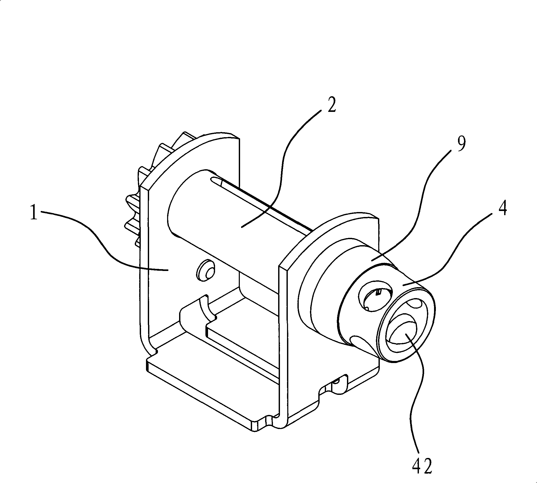
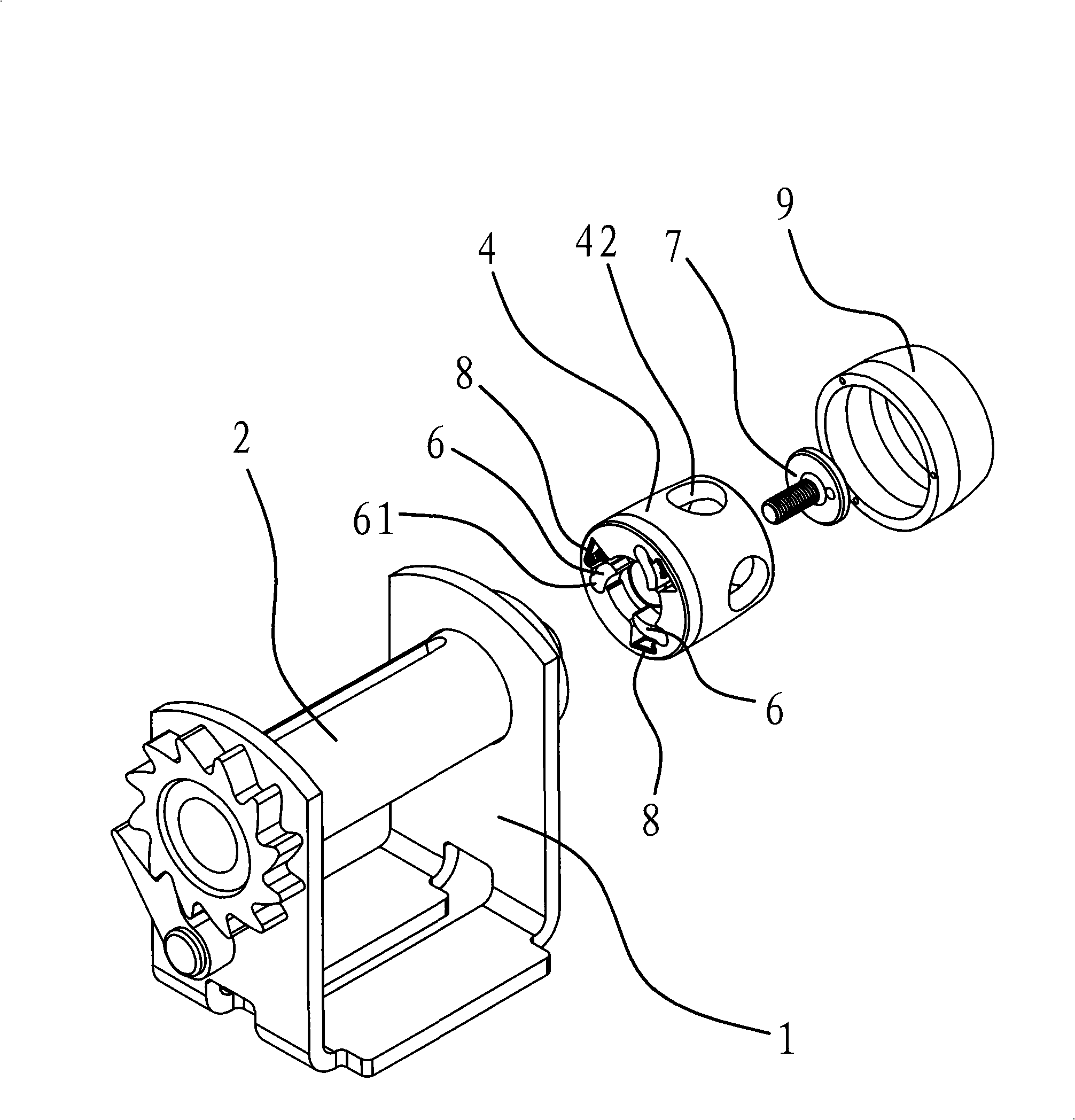
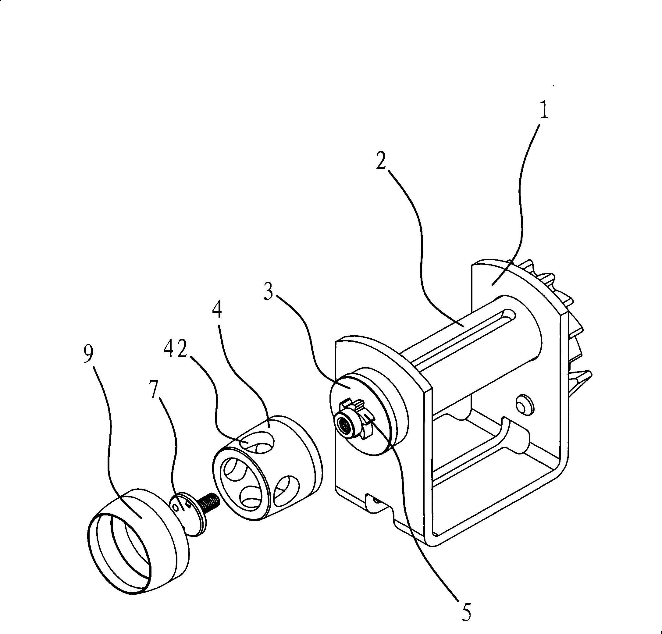
[0029] The winch includes a winch support 1, a belt shaft 2 and a binding belt and the like. The belt shaft 2 is connected to the winch support 1, and the belt shaft 2 can rotate around its axial direction, and the binding belt is wound on the belt shaft 2.

[0030] Such as figure 1 and figure 2 and image 3 and Figure 4 Shown, the fast turning device of this winch band shaft is located at the band shaft 2 extension end of winch support 1 side. This device comprises fixed seat 3, rotating body 4, ratchet 5 and ratchet 6 etc., and fixed seat 3 is fixedly connected in belt shaft 2 ends, and ratchet wheel 5 is fixedly connected in fixed seat 3 ends. The rotating body 4 is cylindrical, the inner end of the rotating body 4 is sleeved on the side of the fixed seat 3 and the rotating body 4 covers the above-mentioned ratchet 5, and the side at the outer end of the rotating body 4 has four evenly distributed Crowbar hole 42. In this embodiment, a set screw 7 is arranged betwee...

Embodiment 2

[0038] The structure and principle of this embodiment are basically the same as those of Embodiment 1, except that the slot 41 has only one retaining edge 41a, and the inner end of the ratchet 6 abuts against the slot under the elastic force of the elastic member 8 41, the inner end of the ratchet 6 cannot be disengaged from the slot 41 under the double action of the stop edge 41a and the elastic member, so that the outer end of the ratchet 6 is against the ratchet 5, see Figure 6 shown. Of course, such a structure can also make the ratchet 6 swing around its inner end.


PUM


Abstract

The invention relates to a hoist zone axis fast rotating device, belonging to machinery technology field, which solves the problem of laboursome operation, time consuming and low seizing efficiency of prior hoist zone axis. The fast rotating device of the gin zone axis is arranged on the zone axis extension end at the lateral part of a gin support, which comprises a permanent seat and a rotating body, wherein the permanent seat is fixedly connected with the zone axis; the lateral part of the permanent seat is sleeve-jointed with the internal end of the rotating body; at least one crowbar hole is positioned at the outer end of the rotating body; the rotating device also comprises a ratchet wheel and a pawl, wherein the ratchet wheel is fixedly connected with the terminal of the permanent seat; a slot is arranged at the inner side of the rotating body, which is clipped on the internal end of the pawl; an elastic member is arranged between the pawl and the inner side of the rotating body; the outer end of the pawl is embedded on the ratchet wheel on the elasticity effect of the elastic member. The hoist zone axis fast rotating device has the advantages of convenient use and high using stability.

Description

technical field [0001] The invention belongs to the technical field of machinery, and relates to a winch, in particular to a fast rotating device for a winch belt shaft. Background technique [0002] In the process of transporting goods by car, the goods usually need to be bundled to prevent the goods from falling off or colliding with each other when the car is driving, resulting in loss or damage. Although the method of directly binding with ropes is very common, it is time-consuming and laborious, and it is difficult to tie the goods tightly. A winch is an advanced lashing tool. It is convenient and safe to use a winch to bind goods, and is very popular among drivers. [0003] Existing winch is usually made up of support, belt shaft and binding belt. The tape shaft is connected to the bracket and the tape shaft is rotatable, and the binding tape is wound on the tape shaft. A crowbar hole is provided at the outer end of the belt shaft protruding out from the bracket. ...

Claims


Application Information

Patent Timeline
Patent Type & Authority Applications(China)
IPC IPC(8): B60P7/06B65H75/34B65B13/02B65B13/18
Inventor 阮卜琴
Owner ZHEJIANG TOPSUN LOGISTIC CONTROL CO LTD
Learn More