
Clamp device with adjustable manipulator angle

A technology of angle adjustment and gripper, which is applied in the direction of chucks, manipulators, manufacturing tools, etc., can solve the problems of easily damaged optical devices and achieve the effect of protecting from damage

Inactive Publication Date: 2008-07-16
SHANGHAI MICRO ELECTRONICS EQUIP (GRP) CO LTD
View PDF1 Cites 9 Cited by
  • Summary
  • Abstract
  • Description
  • Claims
  • Application Information

AI Technical Summary

Problems solved by technology

[0008] The present invention provides a clamping device with adjustable handle angle to solve the disadvantage that the clamping device in the prior art is easy to damage the optical device when clamping the optical device

Method used


Image

  • Clamp device with adjustable manipulator angle
  • Clamp device with adjustable manipulator angle
  • Clamp device with adjustable manipulator angle

Examples


Embodiment Construction

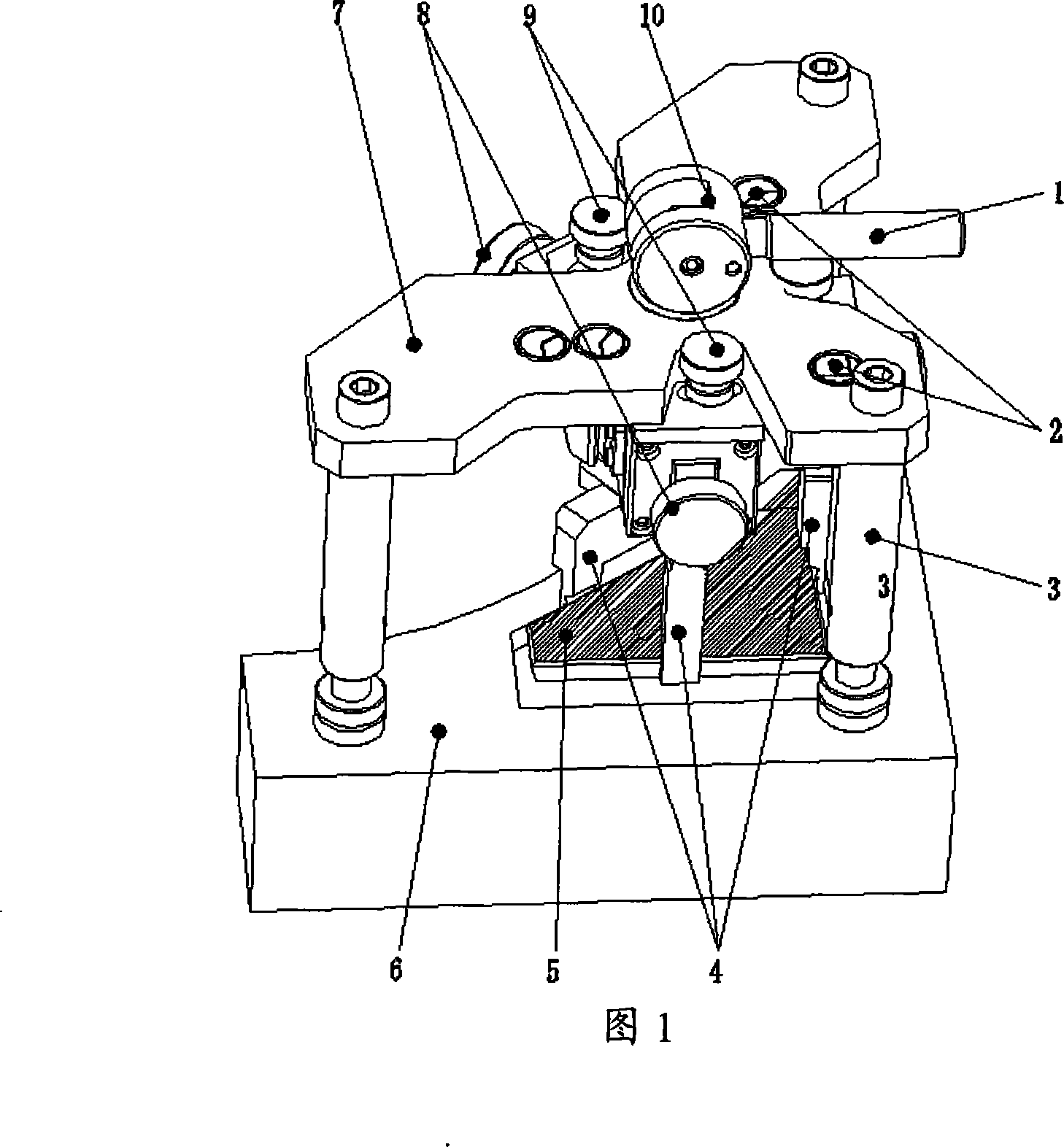
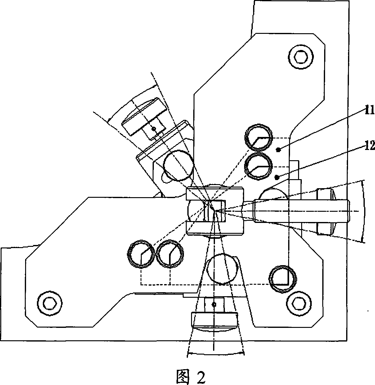
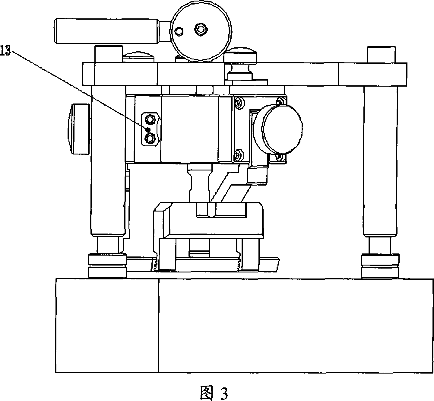
[0041] The clamping device with adjustable gripper angle provided by the present invention will be described in detail below in conjunction with a specific embodiment. As shown in FIG. Standing legs 3 of the device 5, a gripper 4 for grabbing the optics 5, an eccentric lifting mechanism for raising or lowering the gripper 4, a locking mechanism for fixing the gripper 4 and the optics 5 together and An angle adjustment mechanism for adjusting the parallelism between the handle 4 and the side of the optical device 5, wherein the standing leg 3, the handle 4, the eccentric lifting mechanism and the angle lifting mechanism are all fixed on the base plate 7, and the handle 4 is connected with the eccentric lifting mechanism , the angle adjustment mechanism and the locking mechanism are installed on the gripper 4, five pre-alignment mark holes 2 are arranged on the substrate 7, and alignment marks of transparent organic glass are pasted on the mark holes.

[0042] There are three st...


PUM


Abstract

A grasping device with the angle of a griper controllable comprises a baseplate, standing legs, a griper, an eccentric lift mechanism, a clamping mechanism and an angle control mechanism, wherein, the griper, the eccentric lift mechanism and the angle control mechanism are all fixed on the baseplate; the griper is connected with the eccentric lift mechanism; the angle control mechanism and the clamping mechanism are both equipped on the griper and the standing legs are also arranged on to support the baseplate. The invention can not only the grasp optical devices accurately but also protect the optical devices from damage when the grasping force is over large.

Description

technical field [0001] The invention relates to a clamping device, in particular to a clamping device with an adjustable handle angle. Background technique [0002] In high-precision lithography equipment, the shape of the precision alignment optical device used by the workpiece table is polygonal, and the edge angles of different series of devices are generally different. They are made of quartz glass and placed in a groove slightly larger than the size of the optical device. , and fixed on the workpiece table by the magnet on the bottom surface of the optical device. When installing, disassembling or transporting these precision optical devices, the following issues should be fully considered: [0003] First, the surface of the precision optical device cannot be touched, and the gap between the edge of the optical device and the groove is not large. Safe gripping of optics; [0004] Second, the optical device is made of quartz glass, and the optical device is adsorbed a...

Claims


Application Information

Patent Timeline
IPC IPC(8): B25J1/12B25J15/00B25J19/00
Inventor 谢德东袁志扬严天宏
Owner SHANGHAI MICRO ELECTRONICS EQUIP (GRP) CO LTD
Learn More