
Check weigher

A technology for weighing scales and fixing flanges, which is used in the field of calibration scales and can solve the problems of connection technology defects and inability to be cleaned normally.

Inactive Publication Date: 2008-06-25
SARTORIUS AACHEN
View PDF0 Cites 0 Cited by
  • Summary
  • Abstract
  • Description
  • Claims
  • Application Information

AI Technical Summary

Problems solved by technology

Since the accuracy of these scales is greatly affected by the stiffness and degrees of freedom of motion, this form of connection technology has drawbacks
Moreover, this design creates inaccessible voids, which cannot be properly cleaned, which is disadvantageous especially in calibration scales used in the food filling or pharmaceutical industries.

Method used


Image

  • Check weigher
  • Check weigher
  • Check weigher

Examples


Embodiment Construction

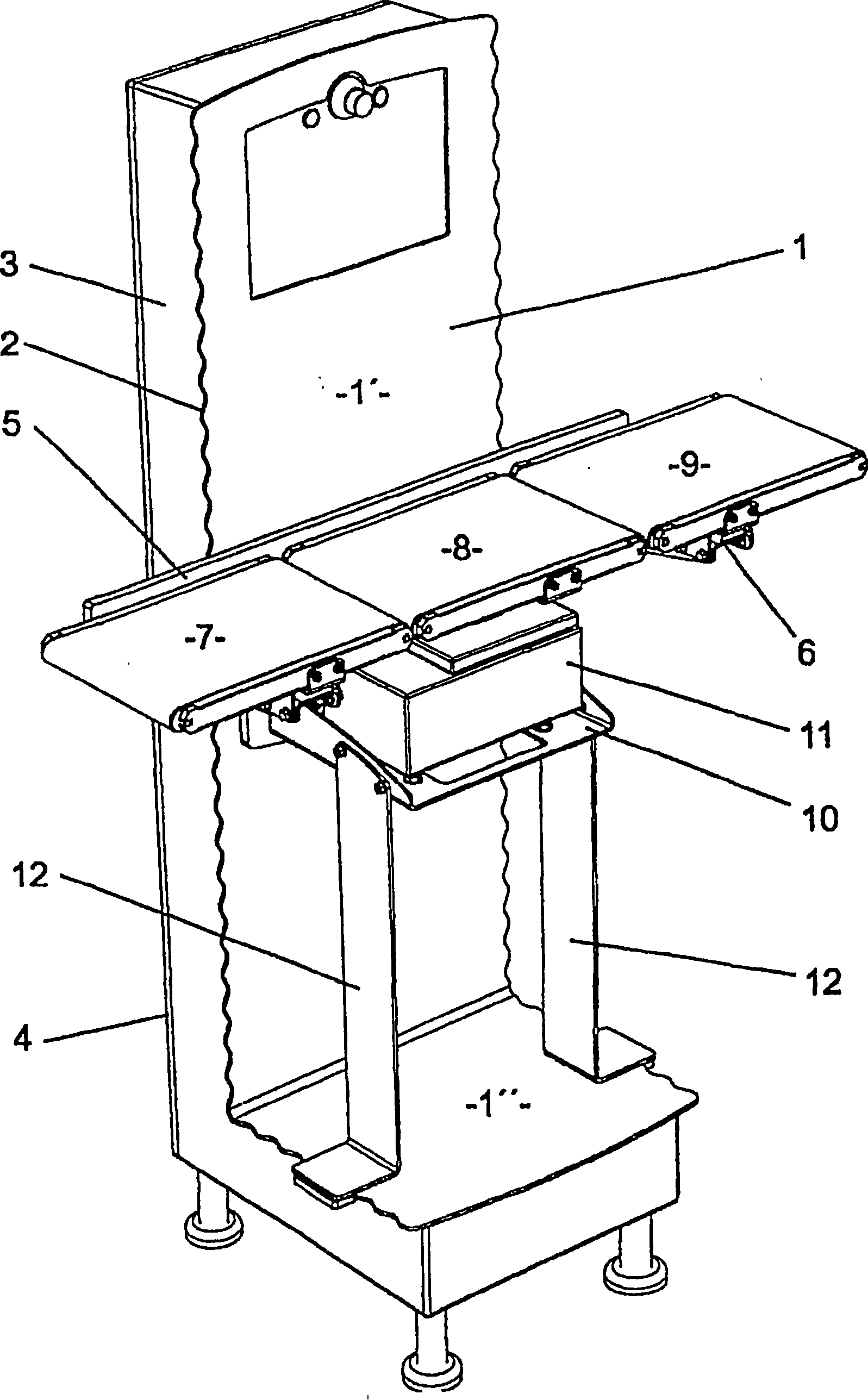
[0033] figure 1 An example of a check scale is shown. It consists of a fixed plate 1 with a fixed flange 2, preferably with vertical struts 1' and horizontal struts 1", detachably or inseparably connected to the fixed plate 1 a metal plate with a rear side door 4 Hollow body 3. The mounting plate 5 is fixed by means of fixing elements, not shown here, on the vertical struts 1' of the fixing plate 1 and carries two conveyor belt brackets 6 on which the conveyor belts 7 and 9 are fixed and Weighing cell bracket 10. The latter bracket holds a weighing cell 11 with a conveyor belt 8 and is optionally connected by a supporting strut 12 to the horizontal strut 1" of the fixed plate.

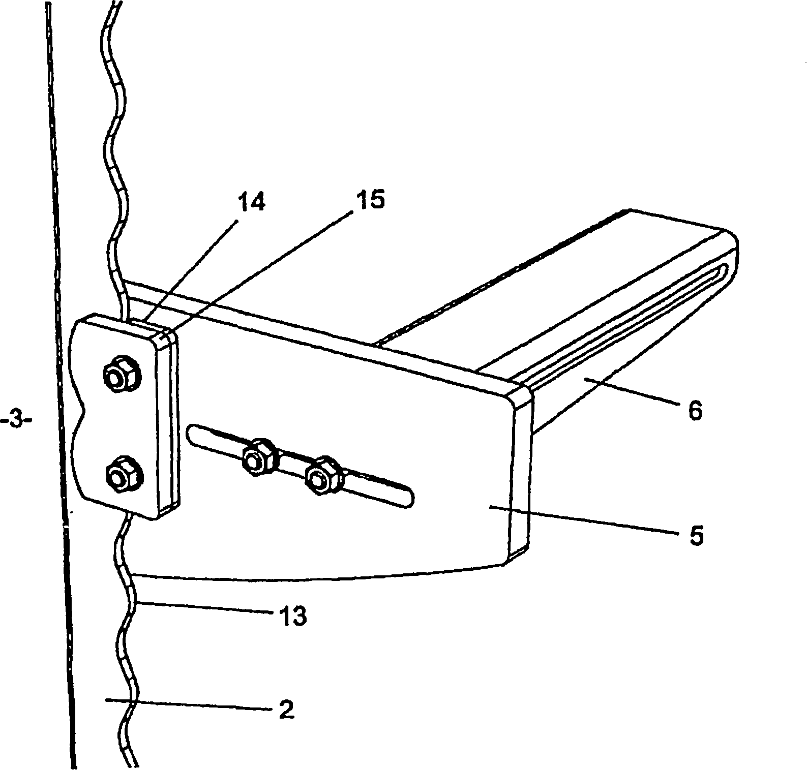
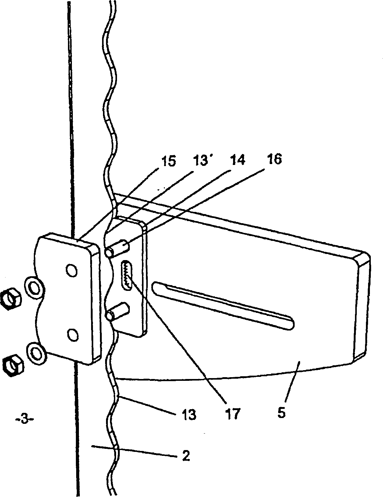
[0034] figure 2 The fixing of the mounting plate 5 and the fixing flange 2 and the arc surface 13 of the fixing flange 2 are shown in detail. This is achieved by the preferably non-detachable clamping plate 14 attached to the mounting plate 5 , whose curved surface 13 ′, not visible here, correspon...


PUM


Abstract

The invention relates to a check weigher comprising a machine body consisting of a front clamping plate and a rear hollow body which is fixedly or detachably connected to said clamping plate and is preferably used as a cabinet for receiving necessary electric and electronic components. The clamping plate is projected on all sides across the hollow body, thereby forming a fastening flange. The outer edge of said fastening flange is provided with a recessed and projected contour which is subdivided into any grid and enables to obtain a positive or non-positive secure connection of accessories with the machine body by means of two clamping plates having a corresponding contour and fixedly connected to a holding plate and additional clamping elements.

Description

technical field [0001] The invention relates to a calibration weighing device with a mechanical body. Background technique [0002] Proof scales are known to comprise a main L-shaped machine body and a variable height weighing transfer table mounted on a vertical portion of the machine body by clamps or screw fastenings. This form of connection technique has drawbacks since the accuracy of these scales is greatly affected by the stiffness and degrees of freedom of movement. Furthermore, this design leads to inaccessible voids, which cannot be properly cleaned, which can be disadvantageous in calibration scales, especially for the food portioning or pharmaceutical industry. Contents of the invention [0003] The object of the present invention is based on providing a calibration scale, the weighing transfer table of which can be precisely fixed on the mechanical body by means of an improved connection technique, thus overcoming the above-mentioned drawbacks. Furthermore, ...

Claims


Application Information

Patent Timeline
IPC IPC(8): G01G19/03
CPCG01G15/00G01G19/035G01G21/28G01G11/003
Inventor 维纳尔·绍尔普
Owner SARTORIUS AACHEN
Learn More