Controller

A technology for control devices and control valves, applied in transportation and packaging, load suspension components, machines/engines, etc., can solve problems such as vacuum grippers passing by the workpiece or passing through the workpiece, damaging the sealing lip, etc.

Active Publication Date: 2011-06-08
J SCHMALZ GMBH
View PDF0 Cites 0 Cited by
  • Summary
  • Abstract
  • Description
  • Claims
  • Application Information

AI Technical Summary

Problems solved by technology

In addition, there is the risk that the vacuum grippers pass by or pass through the workpiece and thus possibly damage the sealing lips on the vacuum grippers.

Method used


Image

  • Controller
  • Controller
  • Controller

Examples


Embodiment Construction

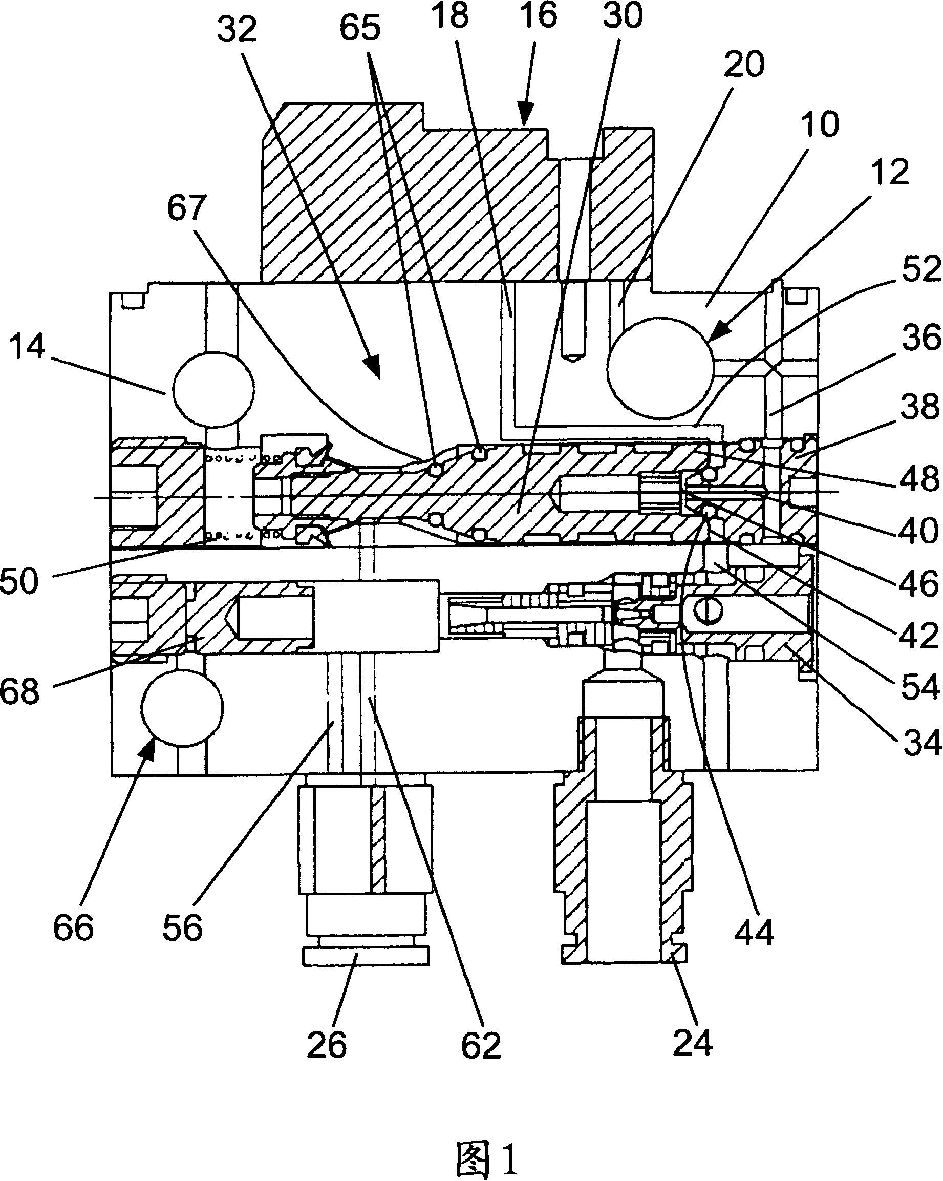
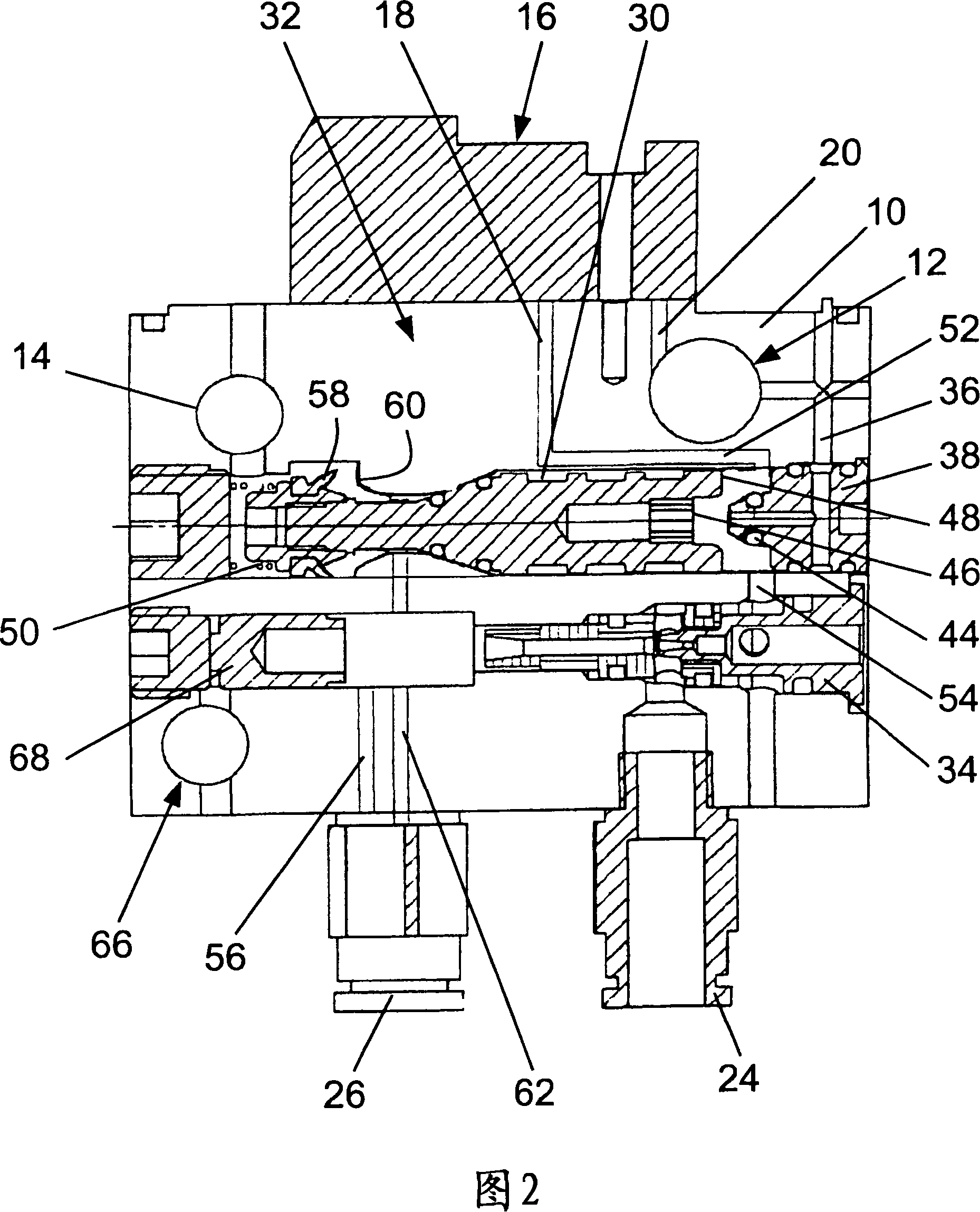
[0027] exist figure 1 and 2 10 shows a valve block, which is constructed as a solid component. The valve block 10 has an inlet 12 for working compressed air and an inlet 14 for working fluid, wherein the inlet 12 is designed as a transverse bore, and the inlet 14 is likewise designed as a transverse bore. These transverse holes have the advantage that multiple valve groups 10 can be figure 1They are arranged consecutively in the viewing direction, so that the inlets 12 and 14 are each aligned with each other, so that all valve groups 10 can be supplied with working compressed air and working fluid together. Furthermore, it can be seen that a pilot valve 16 is mounted on the valve block 10 , with which an input 18 for controlling compressed air is opened and closed. These parts all have the same width (dimension seen in the viewing direction).

[0028] The input 18 has a connection 20 to the input 12 so that the control compressed air can be branched off from the working co...


PUM


Abstract

The present invention relates to a control device for a vacuum clamp holder (22), and the control device includes: an input end (12) of the work compressed air of the eductor (34); an input end (18) for controlling the compressed air of the control value (32); a vacuum connector (24) connected with said vacuum clamp holder (22) and eductor (34), wherein, the control value (32) has a piston (30) capable of moving between the non-operating location and the operating position. The piston remains on the non-operating position by means of reset force loaded on the side of an end and is loaded withwork compressed air against reset force on plane section (46) of the side of the other end of the non-operating position, and the piston has a control surface (48) for controlling the compressed air which is against reset force and is loaded on the control surface (48). The force of the work compressed air on the plane section (46) is smaller than the reset force and the sum of the force of the controlled compressed air on the control surface (48) and the force of the work compressed air on the plane section (46) is bigger than the reset force. As a result, the control value (32) is shifted from the non-operating position to the operating position and then the input end (12) for the work compressed air is connected with the eductor (34).

Description

technical field [0001] The invention relates to a control device for at least one vacuum gripper. Background technique [0002] Vacuum grippers are known in a wide variety of embodiments. They are used to secure objects by means of low pressure so that they can be lifted and sent to another location. In the case of large objects, they can be gripped by several vacuum grippers, on the one hand so that these objects are not deformed, and on the other hand the forces of gravity and the acceleration and deceleration forces occurring during transport are distributed to several vacuums on the holder. For the above purpose, vacuum gripper fields are used, which are equipped with a plurality of individual vacuum grippers and which are placed over the entire surface on the object to be manipulated. If the shape of the object differs from the shape of the vacuum gripper field or if the object has a break, it may happen that the individual vacuum grippers are not covered. These vac...

Claims


Application Information

Patent Timeline
Patent Type & Authority Patents(China)
IPC IPC(8): B65G47/91
CPCB66C1/0218F04F5/52
Inventor 托马斯·艾泽勒里昂哈德·哈特
Owner J SCHMALZ GMBH
Why Eureka
Try Eureka