
Connector prevented from undesired separation of a locking member

一种连接器、锁定件的技术,应用在连接、连接装置的零部件、电气元件等方向,能够解决锁紧弹簧易脱离外壳等问题

Inactive Publication Date: 2008-03-26
JAPAN AVIATION ELECTRONICS IND LTD
View PDF3 Cites 5 Cited by
  • Summary
  • Abstract
  • Description
  • Claims
  • Application Information

AI Technical Summary

Problems solved by technology

In addition, the locking spring is easily disengaged from the housing

Method used


Image

  • Connector prevented from undesired separation of a locking member
  • Connector prevented from undesired separation of a locking member
  • Connector prevented from undesired separation of a locking member

Examples


Embodiment Construction

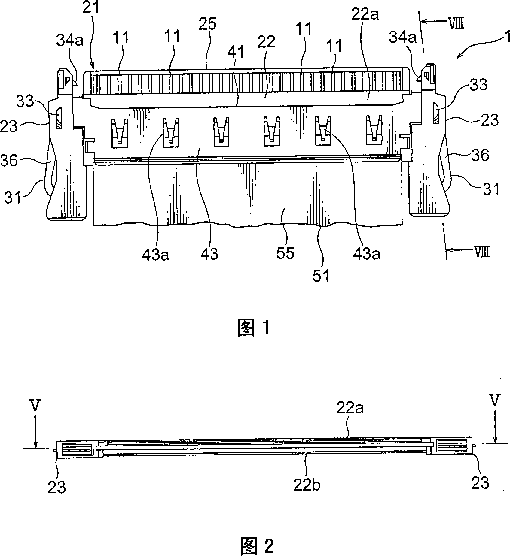
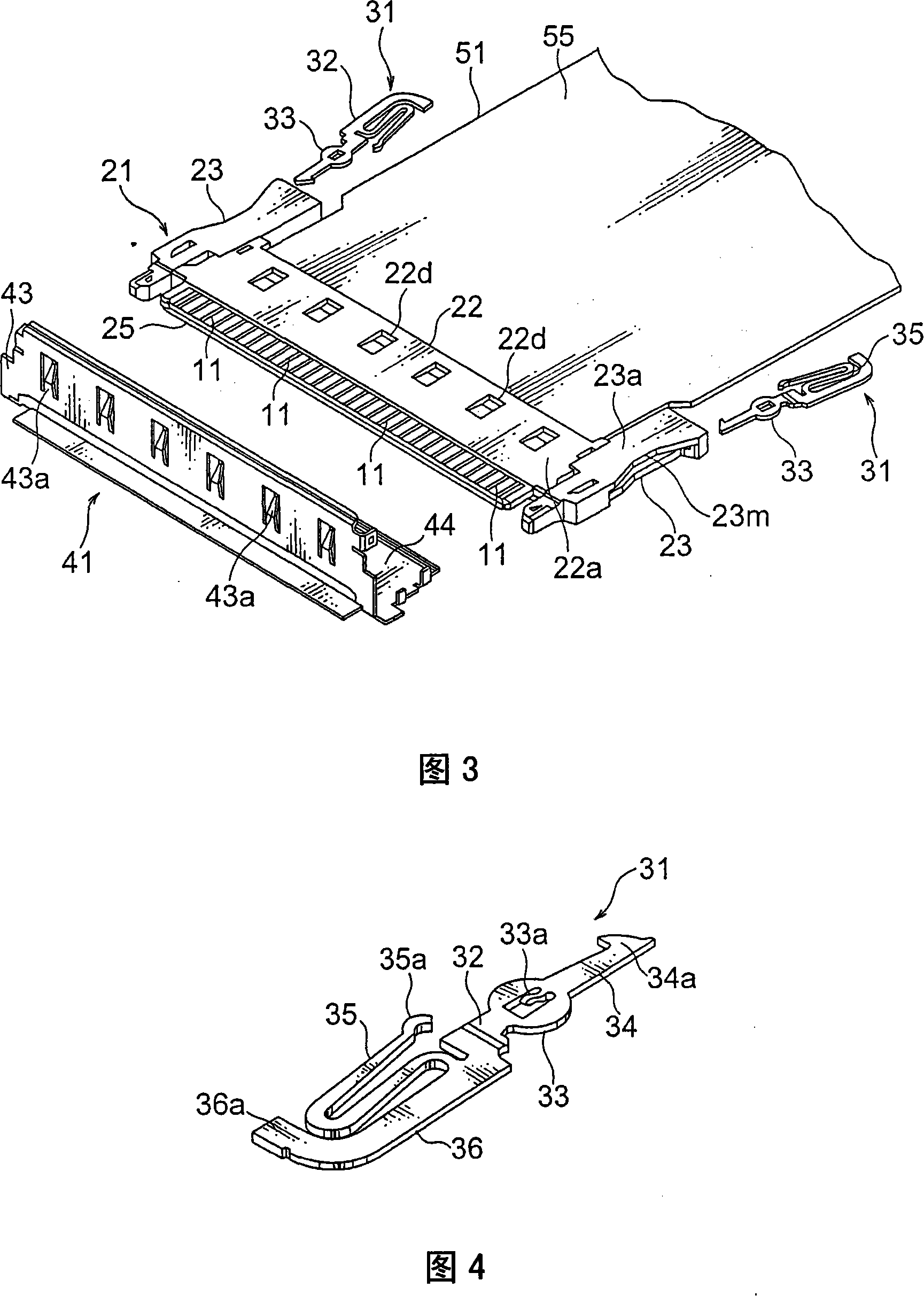
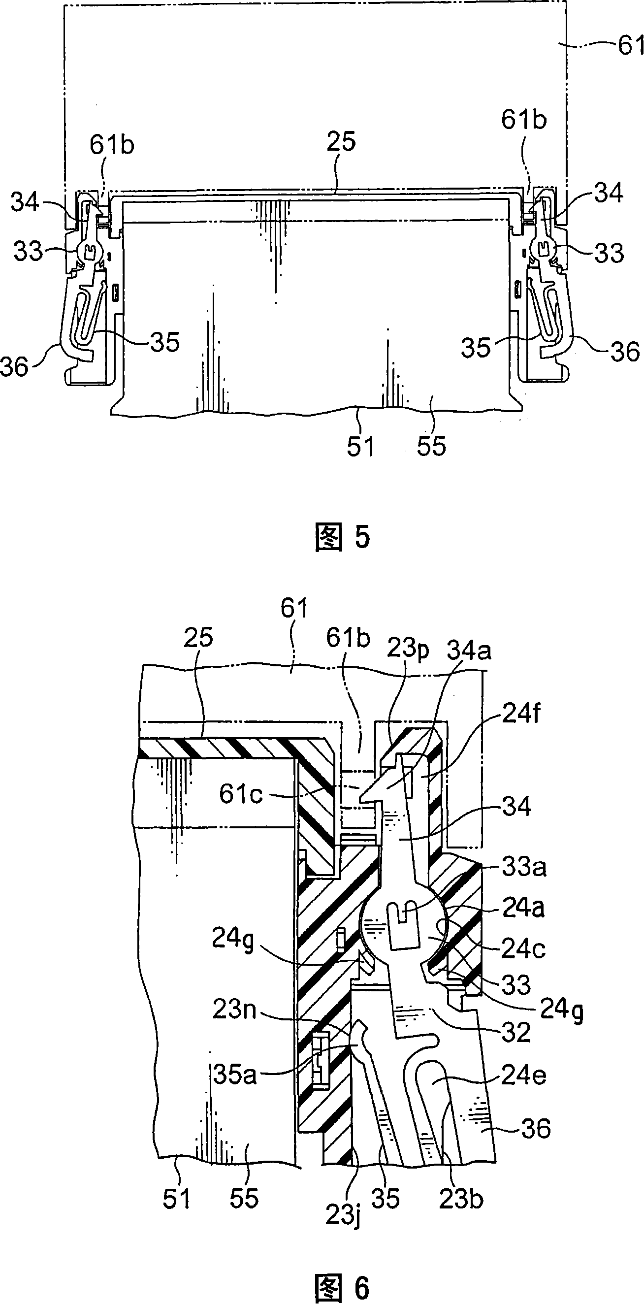
[0020] Referring to FIGS. 1 to 3 , a connector according to an exemplary embodiment of the present invention will be described.

[0021] In FIGS. 1 to 3 , a cable 51 such as an FFC (Flexible Flat Cable) is connected to the connector 1 as a connection object. The cable 51 will be referred to as a flat cable 51 hereinafter. The flat cable 51 includes: a plurality of thin ribbon-shaped conductors (not shown), such as metal foils, which are arranged in parallel to each other with spaces therebetween; and a flexible insulator cover 55 which clamps and holds the conductors.

[0022] The connector 1 includes: a plurality of contacts 11 ; an insulating case 21 holding the contacts 11 ; a pair of locking pieces 31 connected to the case 21 ; and a conductive cover member 41 coupled to the case 21 . The case 21 has: a main body 22 substantially in the shape of a rectangular plate; and a pair of lock receiving portions 23 formed on longitudinally opposite ends of the main body 22 . The ...


PUM


Abstract

A connector includes at least one contact and a shell holding the at least one contact, and a locking member is accommodated in a lock receiving portion of the shell and used to lock a mating state with a mating connector. The lock includes a shaft portion. The lock receiving portion includes a bottom surface opposite to the shaft portion in the axial direction thereof and a side surface for guiding the rotation of the shaft portion. At least one of the lock piece and the lock receiving portion includes a spring portion that presses the shaft portion toward the bottom surface.

Description

[0001] This application is based on and claims priority from Japanese Patent Application No. 2006-256085 filed on September 21, 2006, the disclosure of which is incorporated herein by reference in its entirety. technical field [0002] The invention relates to a connector with a locking piece for locking the mating state between the connector and a mating connector. Background technique [0003] Japanese Invention Patent Application Laid-Open Specification JP-A2005-267970 discloses a connector in which an insulator has a receiving portion adapted to receive a locking mechanism. The lock mechanism described above has: a main body; a locking portion extending from one side of the main body; a spring portion extending from the other side of the main body for continuously pressing the lock in an engagement direction in which the connector engages with the mating connector. a tight part; and an operating part for releasing the locked state by using the locking part. The lock mec...

Claims


Application Information

Patent Timeline
Patent Type & Authority Applications(China)
IPC IPC(8): H01R13/627H01R13/639
CPCH01R13/6275H01R13/639
Inventor 山路崇洋川濑浩司镰田一史
Owner JAPAN AVIATION ELECTRONICS IND LTD
Learn More