
Adjusting board and adjusting device for radiation photography detector camera device

A camera position and adjustment device technology, which is applied to radiological diagnostic instruments, photography, instruments, etc., can solve the problems of inability to count the position adjustment distance, inefficiency, troublesome adjustment, etc.

Inactive Publication Date: 2008-03-19
SHENZHEN LANDWIND IND
View PDF0 Cites 4 Cited by
  • Summary
  • Abstract
  • Description
  • Claims
  • Application Information

AI Technical Summary

Problems solved by technology

[0005] The technical problem to be solved by the present invention is to provide an adjustment plate and an adjustment device for the position of the radiographic detector camera, which overcomes the need for auxiliary tools when adjusting the position of the adjustment device for the position of the radiographic detector camera in the prior art, and the adjustment is troublesome and low-cost. Efficiency and position adjustment distance cannot be counted

Method used


Image

  • Adjusting board and adjusting device for radiation photography detector camera device
  • Adjusting board and adjusting device for radiation photography detector camera device
  • Adjusting board and adjusting device for radiation photography detector camera device

Examples


Embodiment Construction

[0026] Below according to accompanying drawing and embodiment the present invention will be described in further detail:

[0027] As shown in Fig. 7 and Fig. 8, the adjusting plate of the camera position of the radiographic detector of the present invention comprises a moving plate 11 and a fixed plate 12, the fixed plate 12 is fixed on the base 3, and a guide rail is arranged on the fixed plate 12, and on the guide rail There is a dovetail groove, and a spring 10 is arranged in the dovetail groove. One end of the spring 10 is fixed on the moving plate 11 through a bolt 9, and the other end is fixed on the fixed plate 12. The moving plate 11 is provided with a guide rail groove corresponding to the position and shape of the guide rail. , the moving plate 11 and the fixed plate 12 are placed oppositely along the surface where the guide rail and the guide rail groove are located and relatively move along the direction of the guide rail; it also includes an adjustment nut assembly...


PUM


Abstract

An adjusting plate for adjusting the position of the camera in radiography detector comprises a movable plate and a fixed plate which is fixed on a chassis and is provided with a lead rail; the movable plate is provided with a lead-rail groove, the position and shape of the lead-rail groove is matched with that of the lead rail; the movable plate and the fixed plate are positioned opposite to each other along the side on which the leas rail and the lead-rail groove are arranged as well as moving relatively along the lead rail. The present invention also comprises a adjusting nut component, a adjusting handle pole and a adjusting blocking plate; the adjusting nut component is fixed on the fixed plate; the end with threads of the adjusting handle pole is screwed in the nut of the adjusting nut component and the nut can be seen; the adjusting blocking plate is fixed on the fixed plate and can cover the hole position of the nut. An adjusting plate for adjusting the position of the camera in radiography detector comprises a chassis, a bracket and the first adjusting plate; the bracket comprises a first surface and a second surface, and is vertical with and close to each other; the first surface is fixed on the chassis, and the second surface is assembled with the adjusting plate.

Description

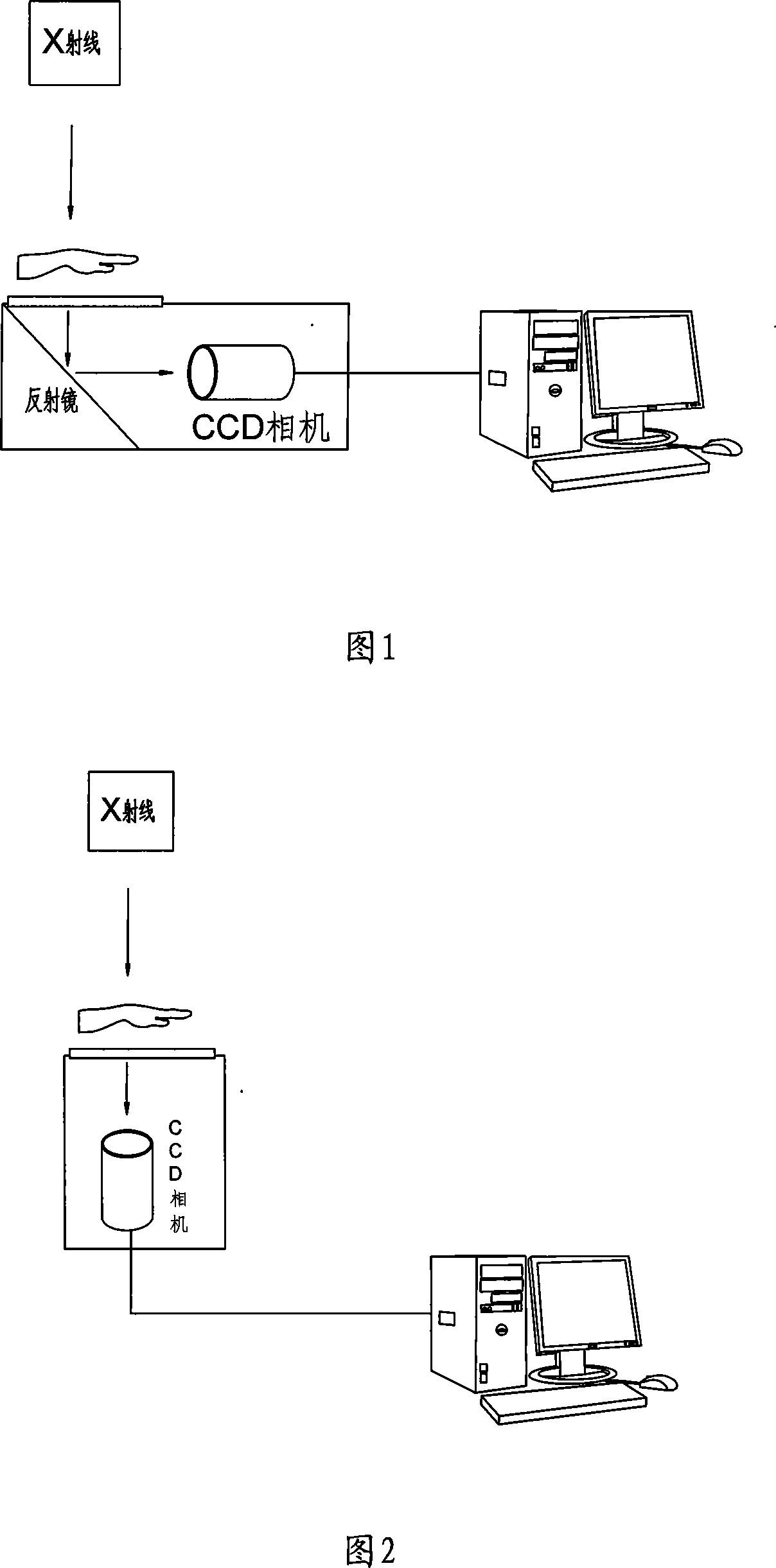
technical field [0001] The invention relates to the technical field of radiographic detectors, in particular to an adjustment plate and an adjustment device for a camera position of a radiographic detector. Background technique [0002] As shown in Figure 1 and Figure 2, the imaging principle of the radiographic detector is: after the radiation penetrates the object (human body, luggage, industrial parts, etc.), the ray projection with image information of the internal structure of the object is projected on the special material. On the scintillation screen, the scintillation screen converts invisible light such as X-rays into visible light, and then this visible light is directly received by the camera or received by the camera after being reflected by the mirror, and the optical signal is converted and transmitted to the image workstation for storage and display. [0003] In the development and production process of radiographic detectors, the test of its optical path syst...

Claims


Application Information

Patent Timeline
Patent Type & Authority Applications(China)
IPC IPC(8): G03B42/02A61B6/00G01N23/04H05G1/02
Inventor 滕久宏
Owner SHENZHEN LANDWIND IND
Learn More