
An inlet device for a fluid fed tangentially into an apparatus

A fluid and inlet technology, applied in the field of inlet devices, can solve the problems of energy consumption, suboptimal and disadvantageous, etc.

Inactive Publication Date: 2008-03-19
SULZER CHEMTECH AG
View PDF5 Cites 14 Cited by
  • Summary
  • Abstract
  • Description
  • Claims
  • Application Information

AI Technical Summary

Problems solved by technology

Therefore, the pressure is restored only to a small extent, and the energy is basically expended
This arrangement is disadvantageous when the pressure in the device is set and must be regulated
In order to counteract this pressure loss, the incoming gas flow must have a higher pressure, and consequently the equipment from which the gas flow originates must work at a higher pressure, which leads to additional requirements concerning the structure and disadvantages related to costs, so This guide vane arrangement is not optimal for any droplet separation

Method used


Image

  • An inlet device for a fluid fed tangentially into an apparatus
  • An inlet device for a fluid fed tangentially into an apparatus

Examples


Embodiment Construction

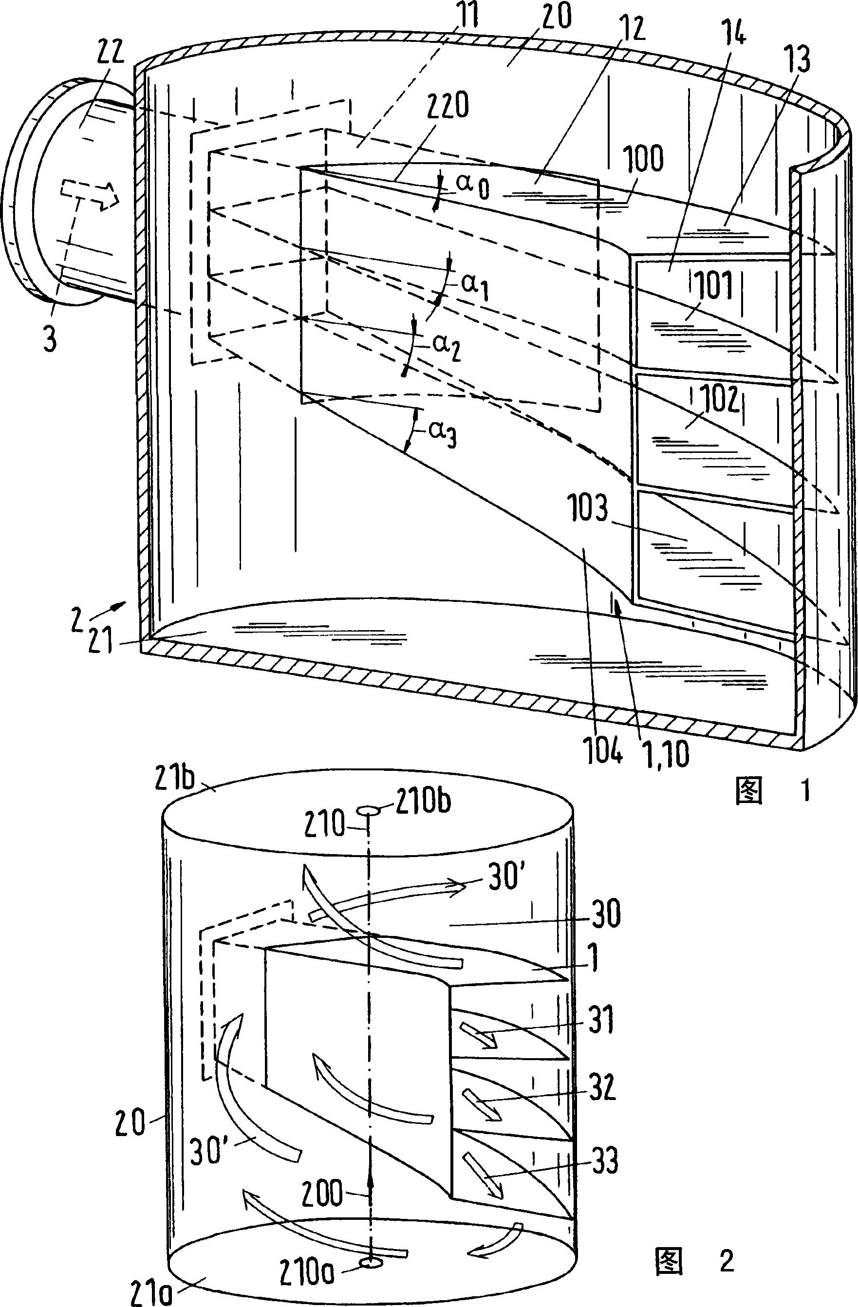
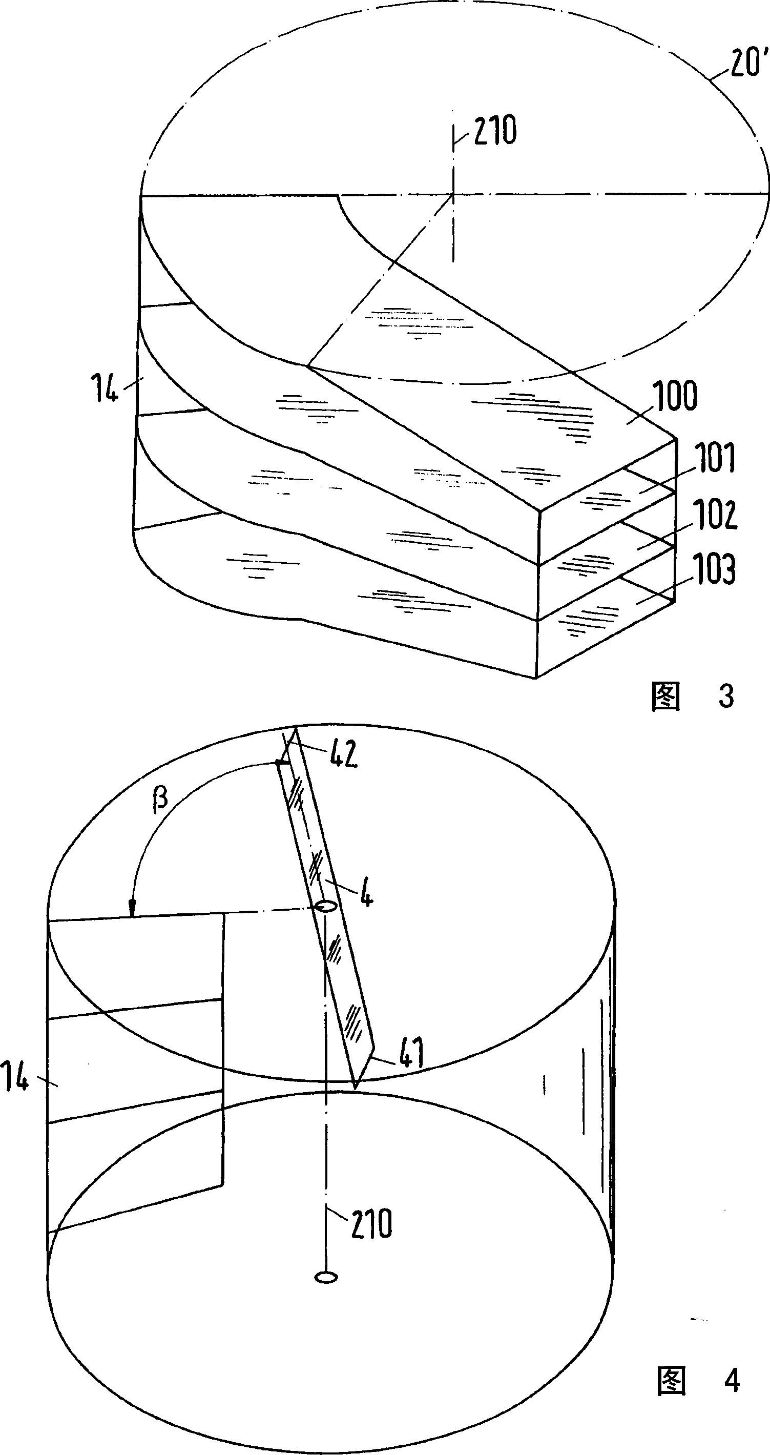
[0021] The fluid 3 flows tangentially into the device 2 , in particular a cartridge, through the inlet arrangement according to the invention as shown in FIGS. 1 and 2 . The sketch in Fig. 2 illustrates a portion of the interior space of the device 2, which is delimited by a perimeter 20, a lower cross-section 21a and an upper cross-section 21b. The center point 210a of the lower cross-section 21a (which corresponds to the base 21 in FIG. 1 ) is connected to the center point 210b of the upper cross-section 21b by a central axis 210 .

[0022] The fluid 3 first flows through the connecting socket 22 and then through the flared duct 10 on the periphery of the device 2 . In the connection socket 22, the cross-sectional surface changes from a circle to a rectangle. Fluid 3 leaves channel portion 10 through discharge region 13 and discharge surface 14 and enters vortex 30 in the direction indicated by arrow 30'. The vortex 30 has an axis of rotation running obliquely or para...


PUM


Abstract

The invention relates to an inlet device (1) with an inlet device (1) for the tangential inflow of a fluid (3) into a device (2), which enters a vortex (30) after flowing through a flared duct section (10) located on the periphery of the device. The vortex rotates about an axis close to the central axis (210) of the device. The central axis is coincident with the main direction (200) of the flowing fluid. Through the discharge area (13) of the channel part, a central flow direction (32) of the fluid is preset, which flow direction is along the periphery and is obliquely opposite to said main direction (200). The middle region (12) - or the inlet region (11) and the middle region - and the outlet region of the channel part are produced in a co-diffused manner. The edge extent of the diffusely produced region is located inside the device and extends over less than half of the perimeter to adjoin the perimeter, preferably less than one-third of the perimeter.

Description

technical field [0001] The invention relates to an inlet arrangement for a device for tangential inflow of fluids according to the preamble of claim 1 , wherein the device is in particular a cartridge. It also relates to a device both having and using an inlet device according to the invention. Background technique [0002] Known from EP-A-1588749 (=P.7446) is a fluid inlet device, that is, an inlet and distribution device for a liquid / vapor mixture, with which a two-phase liquid can be injected into the device, in particular In the cartridge, liquid entrained in the fluid (in entrained droplets) can be separated simultaneously. [0003] A flared duct includes curved guide tabs between two walls positioned horizontally and disposed adjacent the perimeter of the device. Fluid flowing tangentially is split by the guide vane into multi-part flow deflected by the guide vane so that when centrifugal force is utilized, the dense phase of the fluid is at least partially dispersed...

Claims


Application Information

Patent Timeline
Patent Type & Authority Applications(China)
IPC IPC(8): B01D3/32B01D3/30B01D45/16B01J4/00B01J19/00
CPCB01D3/008Y10T137/2109Y10T137/85938Y10T137/86372
Inventor F·穆格利P·谢弗L·格尔菲
Owner SULZER CHEMTECH AG
Learn More