Working machinery

A technology for working machines and machine rooms, which is applied to the field of working machines for roofs, and can solve the problems of smaller openings for inspection, reduced workability, and wasted time.

Active Publication Date: 2012-01-25
NIHON KENKI CO LTD
View PDF8 Cites 0 Cited by
  • Summary
  • Abstract
  • Description
  • Claims
  • Application Information

AI Technical Summary

Problems solved by technology

In this way, the width of the roof will also be limited to a smaller size, and the inspection openings provided on the roof will inevitably become smaller.
[0007] Therefore, the engine cover of the opening for switch inspection is not only kept in an open state where the opening angle (opening angle) cannot be set to a sufficiently large angle, but also the engine cover becomes unstable during maintenance and inspection of the engine in the roof. The problem that the workability at the time of maintenance is reduced due to obstacles
[0008] In addition, in the prior art, when the engine cover is kept in an open state, since it is necessary to manually work the slide bar to be clamped with respect to the clamping portion provided on the other side of the slide rail, there is a problem of locking the engine cover. The problem that the work of keeping the cover open takes time and increases the burden on the operator
[0009] That is, when the operator opens the engine cover, it is necessary to open the engine cover with one hand while holding the slide bar with the other hand and clamping it to the clamping part of the slide rail with manual work, thus using a single Manual operation does not hold the hood open

Method used


Image

  • Working machinery
  • Working machinery
  • Working machinery

Examples


Embodiment Construction

[0033] Hereinafter, a detailed description will be given with reference to the drawings and taking a case where the work machine of the embodiment of the present invention is applied to a hydraulic excavator as an example.

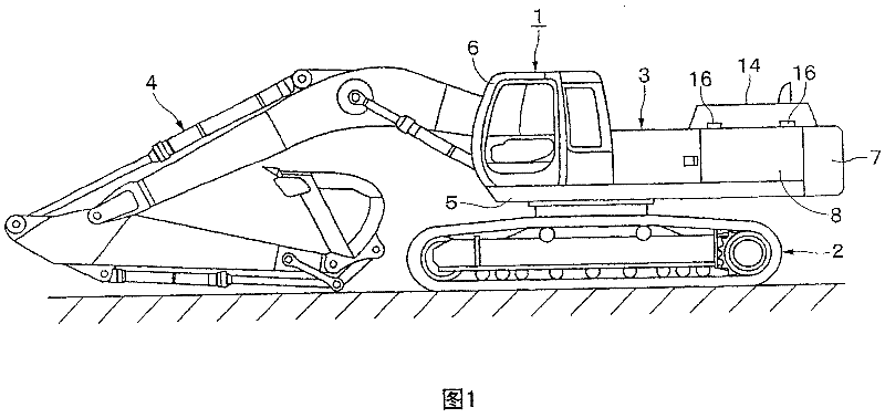
[0034] Here, Figure 1 to Figure 11 This shows the first embodiment of the present invention. In the figure, the mark 1 is a hydraulic excavator as a working machine. The general structure of the hydraulic excavator 1 includes: figure 1 As shown, the crawler-type lower body 2 that can travel automatically; the upper rotating body 3 rotatably loaded on the lower body 2; and the upper part is movably installed up and down for excavation work such as sand and soil The working device 4 at the front of the rotating body 3.

[0035] In this case, the upper rotating body 3 of the hydraulic excavator 1 and the lower traveling body 2 constitute the vehicle body of the work machine. The upper rotating body 3 is composed of a rotating frame 5, a cab 6, a counterweight 7,...


PUM


Abstract

To hold an engine cover in a door opening state by operation of only one hand, and to ensure a large opening angle in the door opening state.A guide hole 28 made from a long linear guide portion 28A and a V-shaped guide 28B is provided on a stay guide 27 of a door opening holding mechanism 21. A first bending portion 28B1 of the V-shaped guide portion 28B is formed so as to curve along a moving track 25 when a tip end side of a stay 22 rises and falls at a position on an opposite side to the linear guide portion 28A. A second bending portion 28B2 is formed from an end portion of the first bending portion 28B1 to have a shape which is generally bent in a V-shape, and extends outward in a diameter direction of the moving track 25 in regard to the first bending portion 28B1. When the engine cover 14 is held in the door opening state, the tip end side of the stay 22 is hooked to the second bending portion 28B2 to be locked.

Description

Technical field [0001] The present invention relates to a working machine suitable for use as a construction machine such as a hydraulic excavator, a crane, a wheel loader, a forklift, or a handling machine, and more particularly to a working machine equipped with a roof that houses a power source such as an engine. Background technique [0002] Generally, in working machines (construction machines) such as hydraulic excavators, a structure is adopted in which a roof is provided on the frame of the vehicle body, and the roof forms a machine room for accommodating power sources such as engines. In addition, a structure is adopted such that an opening for inspection of the engine in the maintenance and inspection machine room is provided in the upper part of the roof, and the opening is opened and closed by an engine cover (engine cover) (for example, refer to Patent Document 1 Open Bulletin 2001-180526). [0003] In addition, a sliding rod (support rod) and a sliding rail (support ...

Claims


Application Information

Patent Timeline
Patent Type & Authority Patents(China)
IPC IPC(8): E02F9/00
CPCE02F9/00E02F9/0866E02F9/0891E02F9/08E02F9/18
Inventor 津久井洋熊谷博
Owner NIHON KENKI CO LTD
Why Eureka
Try Eureka