Viewing device for industrial process transmitters

A technology for industrial processes and observation devices, applied in the direction of measuring devices, instruments, scientific instruments, etc., can solve the problem of not being enough to allow observation of local display devices

Active Publication Date: 2008-03-05
ROSEMOUNT INC
View PDF0 Cites 0 Cited by
  • Summary
  • Abstract
  • Description
  • Claims
  • Application Information

AI Technical Summary

Problems solved by technology

If the selected industrial transmitter does not match the installation location, or if the equipment surrounding the installation location is variable, the range of display directions may not be sufficient to allow viewing of the local display unit

Method used


Image

  • Viewing device for industrial process transmitters
  • Viewing device for industrial process transmitters
  • Viewing device for industrial process transmitters

Examples


Embodiment Construction

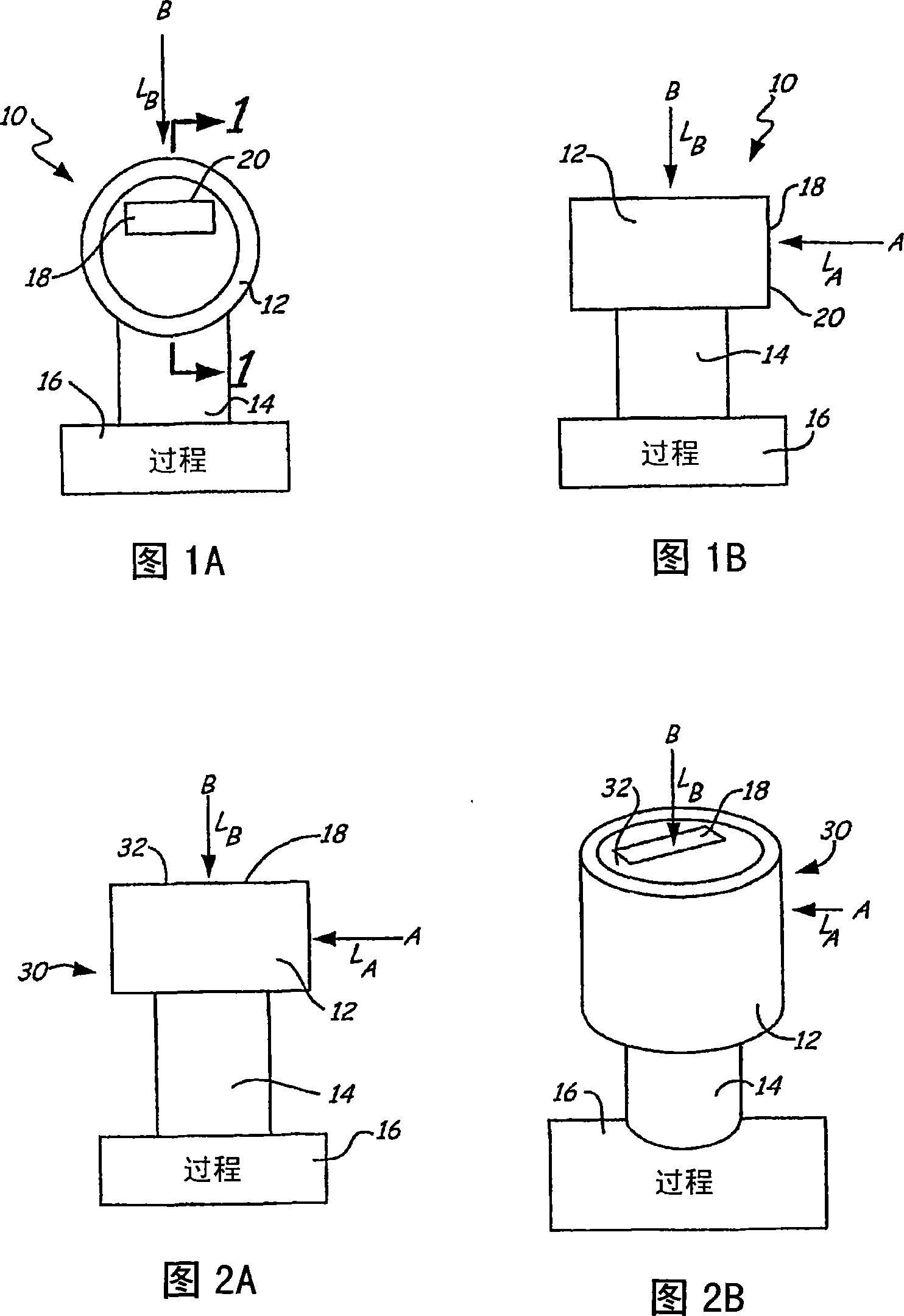
[0018] The viewing device according to the present invention can be used to assist viewing local display devices contained in industrial transmitters of any type and configuration known in the art. Figures 1A-2B illustrate two common industrial transmitter configurations.

[0019] 1A and 1B illustrate the industrial transmitter 10 , wherein FIG. 1A is a front view of the industrial transmitter 10 and FIG. 1B is a side view of the industrial transmitter 10 . The industrial transmitter 10 includes an electronics housing 12 attached to a sensor module 14 . The sensor module 14 is in communication with the industrial process 16 and includes at least one sensor (not shown) for sensing a parameter related to the industrial process 16 . Examples of sensed parameters include pressure, temperature, pH, flow properties (eg, flow rate), viscosity, density, concentration, and liquid level. Electronics housing 12 houses electronics (not shown) that communicate with the sensors in sensor ...


PUM


Abstract

The present invention is a viewing device (40) for positioning in front of a locay display (18) of an industrial transmitter (10). The viewing device (40) has optics (42) that receive light from the local display (18) along a first line of sight, redirect the light, and transmit the light along a second line of sight. The second line of sight is disposed at an angle relative to the first line of sight.

Description

technical field [0001] The present invention generally relates to field devices for monitoring industrial processes. In particular, the present invention relates to a viewing device to aid in viewing a display device on an industrial process transmitter. Background technique [0002] Transmitters for industrial processes typically include an electronics housing and a sensor module attached to the electronics housing. The sensor module is designed to be sensitive to parameters relevant to industrial processes, such as pressure, temperature, density, concentration, flow properties, liquid level, pH and viscosity. These industrial transmitters often include local display devices, such as liquid crystal displays (LCDs), contained within the electronics housing, allowing supervisory personnel to view information related to the sensed quantity. Industrial transmitters are often placed in crowded locations or in different orientations than expected, so viewing local displays can ...

Claims


Application Information

Patent Timeline
Patent Type & Authority Applications(China)
IPC IPC(8): G02B17/00
CPCG02B17/026G01K1/06
Inventor 戴维·A·布罗登
Owner ROSEMOUNT INC
Why Eureka
Try Eureka