Centre pin type guiding compelling radial direction mechanism

A force-guided, pin-type technology, applied in the self-adjustment direction of the wheel shaft, can solve the problems of large wheel flange wear, poor guiding performance, and affecting the speed and stability of rail vehicles, and achieves the reduction of longitudinal positioning stiffness and wide application range. The effect of reducing noise

Active Publication Date: 2008-02-06
CRRC QINGDAO SIFANG CO LTD
View PDF0 Cites 3 Cited by
  • Summary
  • Abstract
  • Description
  • Claims
  • Application Information

AI Technical Summary

Problems solved by technology

The bogie driven by the center pin has poor guiding performance on a specific curve, and its guiding gain design is unreasonable, and the matching between the bogie wheel set and the track is not optimal, resulting in greater wheel rim wear
[0005] To sum up the above-mentioned problems that affect the speed and stability of rail vehicles are that the existing radial bogies lack flexible guiding performance, and the unity of forced guiding and self-guiding cannot be realized on a specific curve.

Method used


Image

  • Centre pin type guiding compelling radial direction mechanism
  • Centre pin type guiding compelling radial direction mechanism
  • Centre pin type guiding compelling radial direction mechanism

Examples


Embodiment 1

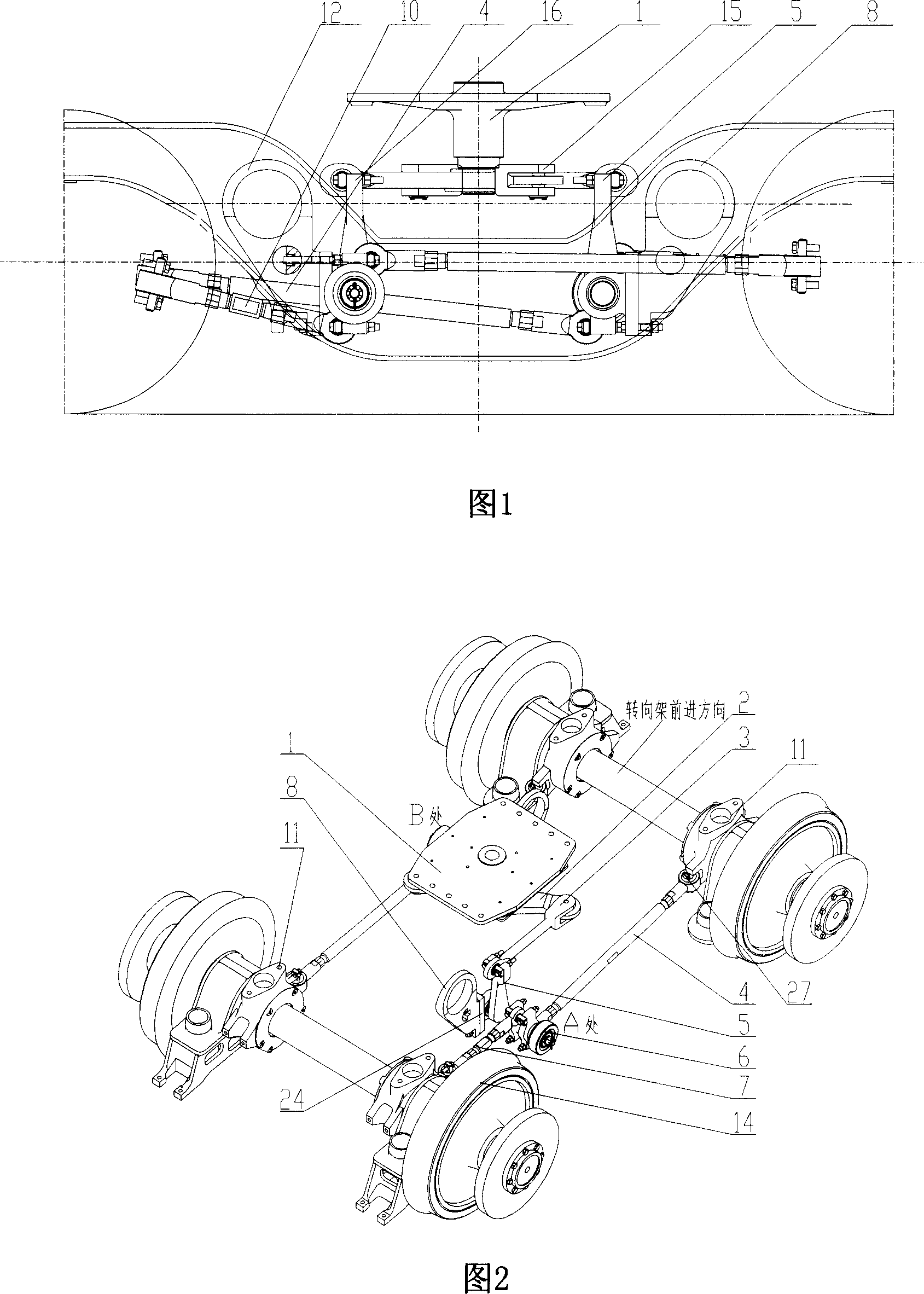
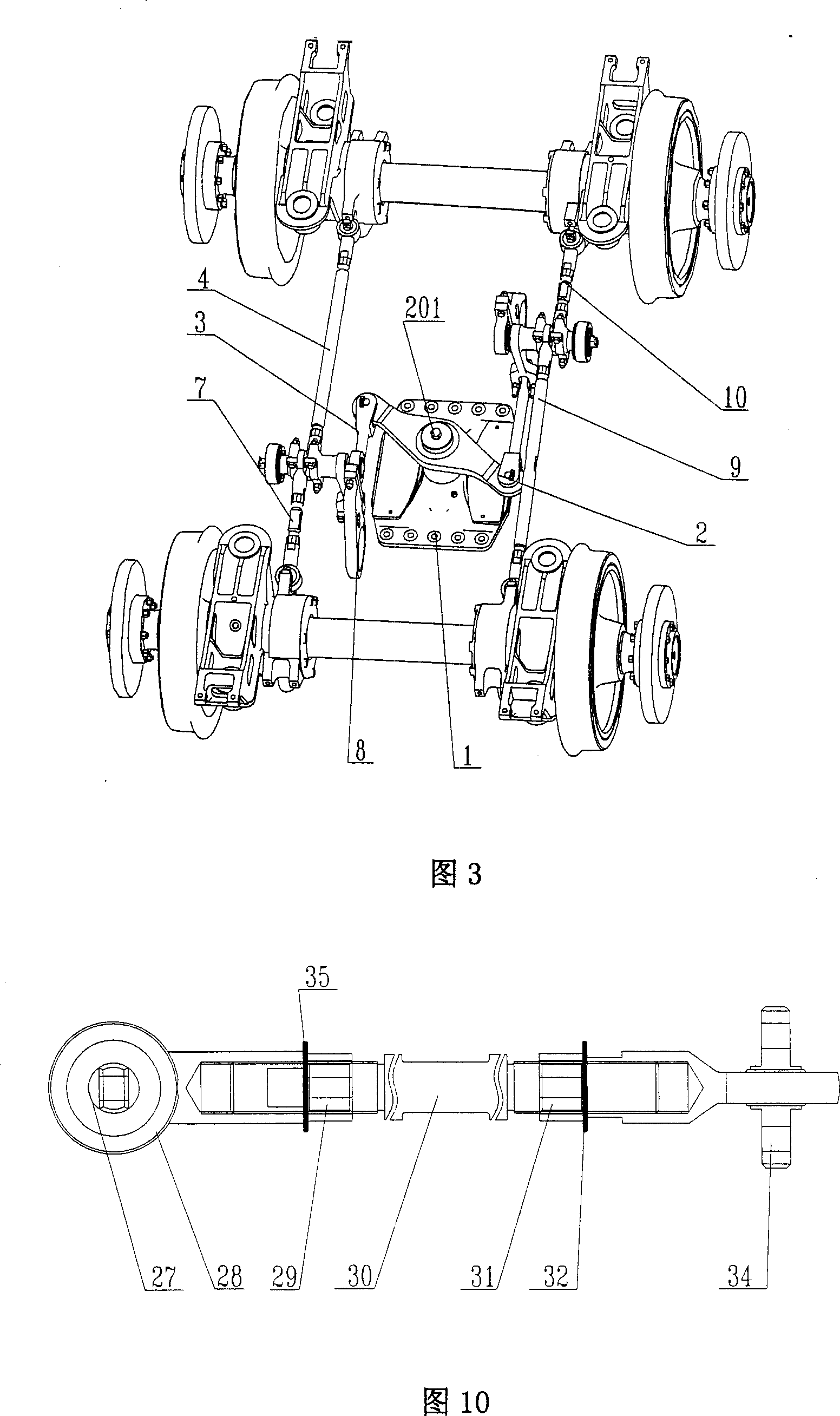
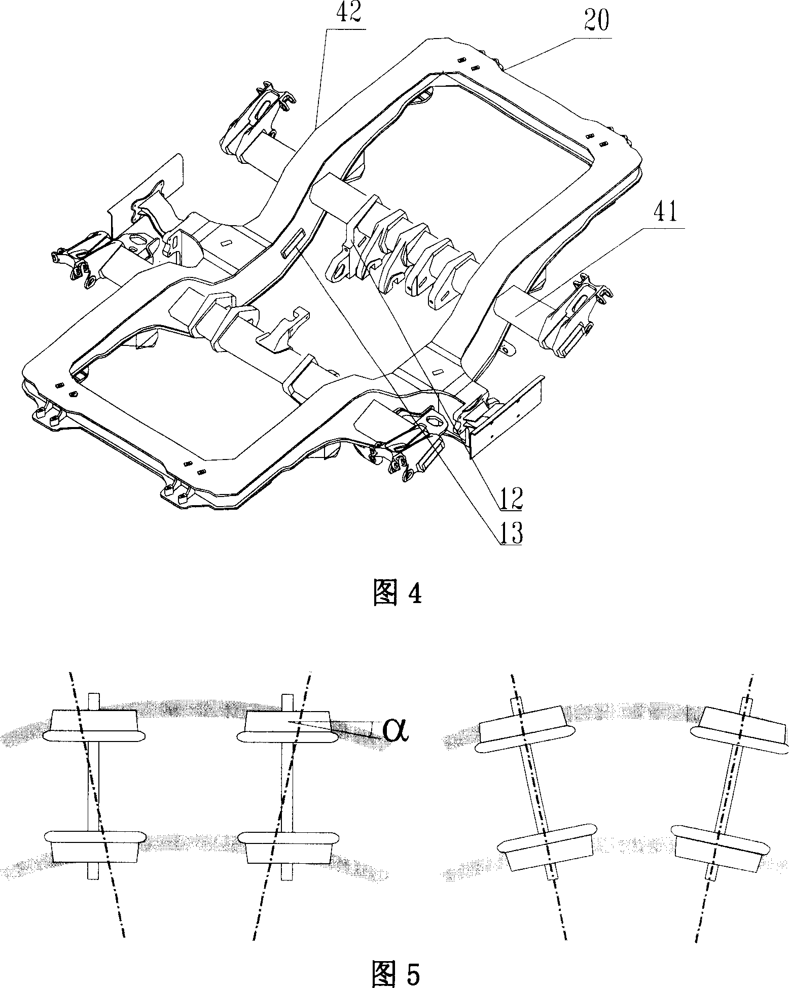
[0046] Embodiment 1, as shown in Figures 1 to 10, the central pin type forced radial mechanism of the present invention is applied to a power bogie 20 with two shafts and the traction mode is center pin traction, and the bogie 20 has two groups wheelset 14, and elastically supports a body 18 of a railway vehicle assembly 19. In this embodiment, the railway vehicle 19 is an urban rail vehicle with its own power.

[0047] The central pin type is forced to a radial mechanism, and passes through the central pin 1 and the vehicle body 18 .

[0048] The radial adjustment mechanism has a central turntable 2, which is connected to the bottom of the center pin 1 through a spline 201 and moves together with the center pin 1 .

[0049] A group of longitudinal push rods 3 and 15 are respectively connected to the end of the central turntable 2, and the other ends are connected to the rotating arms 5 and 16 respectively.

[0050] The pivoting arms 5 and 16 are connected respectively and f...


PUM


Abstract

The central pin type forced steering radial mechanism has a radial truck which has forced steering, self steering and flexible steering performance. A novel radial adjustment mechanism is adopted to reduce the longitudinal positioning rigidity of a wheel pair opposite frame and to enable wheel pairs to approach in the radius direction as much as possible when the truck passes through a curve, thereby reducing noise and abrasion and increasing the adhesive force of the curve. The central pin type forced steering radial mechanism is provided with a frame, the truck is connected with a car body through the central pin and supports the car body upward and elastically, and the central pin type forced steering radial mechanism is also provided with two sets of wheel pairs and the radial adjustment mechanism. The radial adjustment mechanism is provided with a central rotating disc, a group of vertical push rods are respectively connected with the end part of the central rotating disc, and the other end of each vertical push rod is connected with a rotating arm. The rotating arm is connected with a positioning sleeve and forms a first positioning point on the truck side sill through the positioning sleeve, and the rotating arm is connected with the positioning sleeve and forms a second positioning point on the truck transom through the positioning sleeve. Two sets of tie rods are respectively connected with the ratating arm, and the other end of the each tie rod is connected with the axle box of front and rear wheel pairs.

Description

technical field [0001] The invention relates to a radial mechanism for a rail vehicle bogie, in particular to a center pin type forced guide radial mechanism, which belongs to the field of mechanical manufacturing. Background technique [0002] With the overall speed-up of my country's railway traffic and the rapid development of urban light rail and rail transit, locomotives operating at high speeds have put forward higher requirements for bogie structures and operating safety. [0003] The bogie of a rail vehicle is a rigid frame that fixes the front and rear wheel sets. The existing bogies that are applied to two axles and whose traction mode is center pin traction basically adopt the guiding mechanism of center pin torsion arm and horizontal connecting rod. The wheel set Compared with the frame, it has a large longitudinal positioning stiffness. Therefore, when the bogie passes through a curve, the two wheelsets on a bogie are basically kept parallel, so that an angle o...

Claims


Application Information

Patent Timeline
Patent Type & Authority Applications(China)
IPC IPC(8): B61F5/38
Inventor 宋晓文李言义乔青峰
Owner CRRC QINGDAO SIFANG CO LTD
Why Eureka
Try Eureka