
Vibration mirror motor

A galvanometer motor and rotor technology, applied in electric components, electrical components, electromechanical devices, etc., can solve the problems of limited response speed, low axial stiffness, affecting running accuracy, etc., to achieve positioning, eliminate drift, and improve performance. Effect

Active Publication Date: 2010-07-14
HANS LASER TECH IND GRP CO LTD +1
View PDF9 Cites 1 Cited by
  • Summary
  • Abstract
  • Description
  • Claims
  • Application Information

AI Technical Summary

Problems solved by technology

Traditionally, the position feedback used by the vibrating mirror motor mostly adopts capacitive or inductive sensors. Due to the drift of these sensors, the accuracy, repeatability and stability of the vibrating mirror motor are greatly restricted.
In addition, the galvanometer motor is a two-pole structure and supported by ball bearings, the relatively low moment / inertia ratio limits the response speed, and the low axial stiffness also affects its running accuracy

Method used


Image

  • Vibration mirror motor
  • Vibration mirror motor
  • Vibration mirror motor

Examples


Embodiment Construction

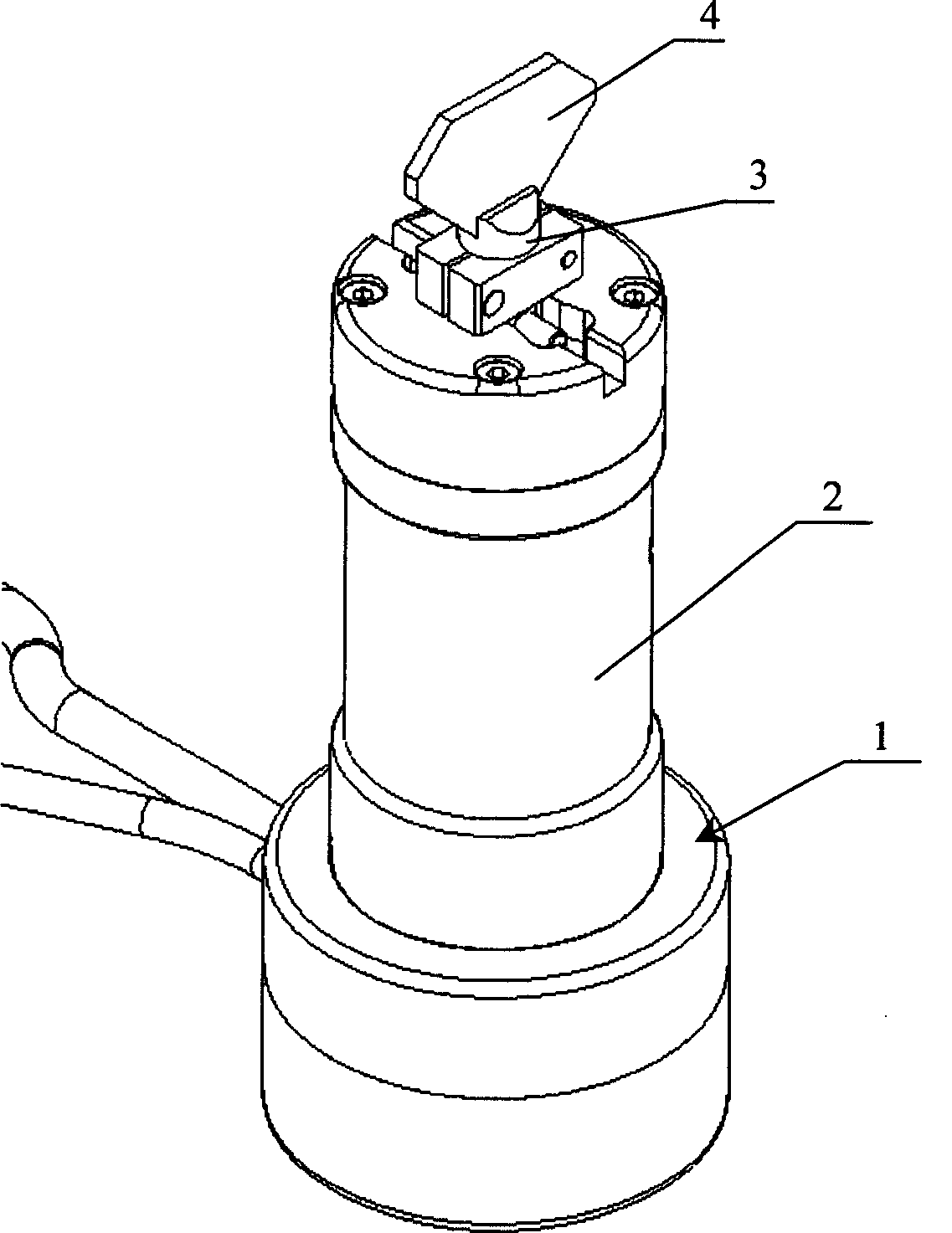
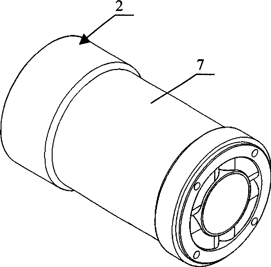
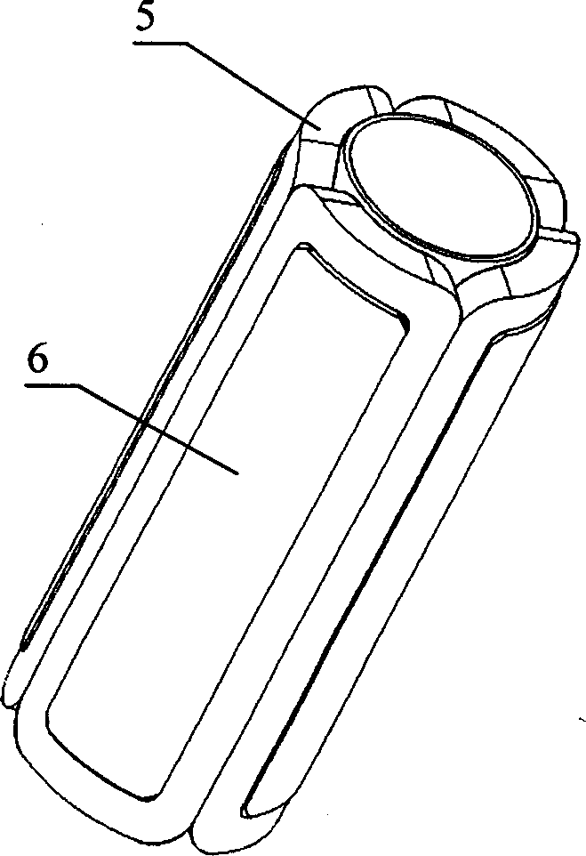
[0023] Such as Figure 1-Figure 6 As shown, the vibrating mirror motor 1 of the present invention includes a fixed stator 2 and a rotor 3 that rotates relative to the stator 2 . Among them, the stator 2 includes a coil 5, a skeleton 6 and a yoke 7. The skeleton 6 is made of a non-magnetic material, and long slots are arranged on it at intervals. For the multi-pole winding, the coil 5 and the skeleton 6 are vacuum-cast in the yoke 7 by epoxy resin. The rotor 3 includes a magnet 8, a rotating shaft 9 and a bearing 10. A plurality of magnets 8 with alternating polarities are pasted on the magnetic rotating shaft 9 to form a multi-pole rotor. The magnetic rotating shaft 9 includes a main shaft (not shown) covered by the magnet 8, which is High magnetic permeability material, the two ends are respectively connected to non-magnetic shaft extensions 11 and 12, the bearing 10 is an angular contact ball bearing, installed on the non-magnetic shaft extensions 11 and 12, and the compres...


PUM


Abstract

The invention relates to a vibration mirror electric machine, comprising stator, rotor rotating relative to the stator, and position feedback device for feeding back rotation position of the rotor, where the position feedback device is a grating encoder. And it uses the grating encoder to eliminate the problem that system performance is not stable caused by zero position and gain drift of traditional capacitance or inductance vibration mirror electric machine. Besides, it adopts multipolar slotless electric machine structure to increase response speed of the vibration mirror electric machine.

Description

【Technical field】 [0001] The invention relates to a motor, in particular to a moving magnet vibrating mirror motor that can be used in laser marking, optical scanning or similar systems. 【technical background】 [0002] Vibrating mirror motors usually have different structural forms and configurations. Traditionally, the position feedback used by the vibrating mirror motor mostly uses capacitive or inductive sensors. Due to the drift of these sensors, the accuracy, repeatability and stability of the vibrating mirror motor are greatly restricted. In addition, the vibrating mirror motor is a two-pole structure and supported by ball bearings. The relatively low torque / inertia ratio limits the response speed, and the low axial stiffness also affects its running accuracy. 【Content of invention】 [0003] The technical problem to be solved by the present invention is to provide a moving magnet vibrating mirror motor controlled by a grating encoder, so as to eliminate the unstable...

Claims


Application Information

Patent Timeline
Patent Type & Authority Patents(China)
IPC IPC(8): H02K29/10H02K33/00H02K1/22H02K5/00
Inventor 高云峰廖有用王光能付晓辉
Owner HANS LASER TECH IND GRP CO LTD
Learn More