
Device for monitoring micro-particles shapes and dispersion based on image

A technology of image monitoring and microparticles, applied in the field of optics, can solve the problems of large amount of calculation, difficult development, and time-consuming, etc., and achieve the effect of improving the sensitivity of optical fibers

Inactive Publication Date: 2010-12-29
ANHUI INST OF OPTICS & FINE MECHANICS - CHINESE ACAD OF SCI
View PDF2 Cites 0 Cited by
  • Summary
  • Abstract
  • Description
  • Claims
  • Application Information

AI Technical Summary

Problems solved by technology

For particle shape analysis, it was difficult in the past to develop a rapid and routine method to achieve
Since the scattered light of particles is a function of many factors such as particle shape, it is a technique that is often tried. However, to obtain accurate inversion shape, the amount of calculation is relatively large; traditionally, microscopes are also commonly used for this work. And as the only instrument that can observe individual particles and analyze their size and shape, due to their absolute nature, microscopy is often used to confirm the results of other techniques, however, to obtain statistically meaningful results, it takes a lot of time to carry out samples preparation, observation

Method used


Image

  • Device for monitoring micro-particles shapes and dispersion based on image
  • Device for monitoring micro-particles shapes and dispersion based on image
  • Device for monitoring micro-particles shapes and dispersion based on image

Examples


Embodiment Construction

[0027] See attached picture.

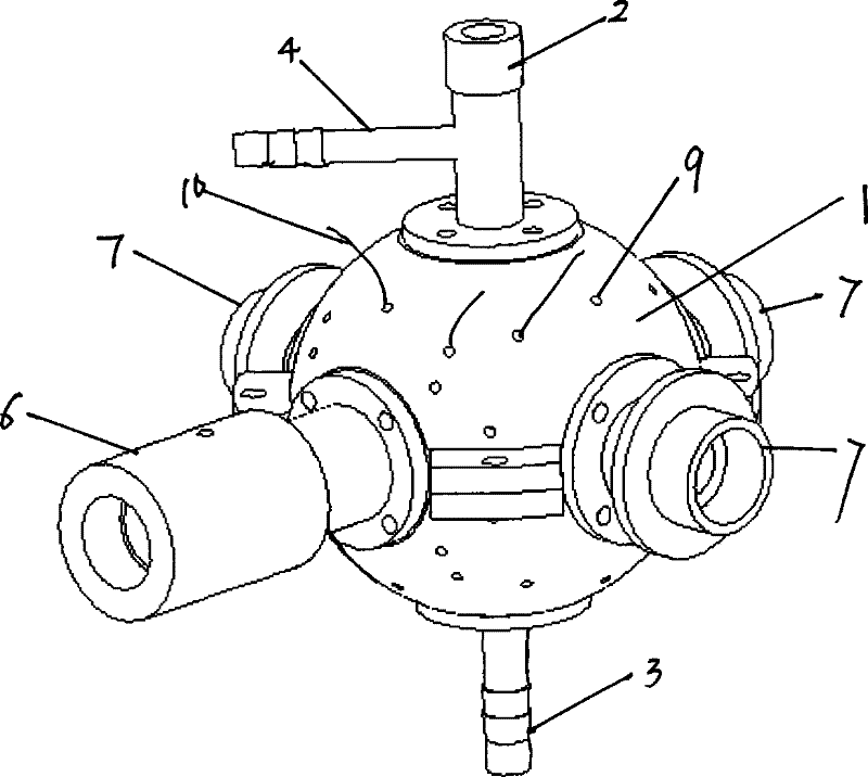
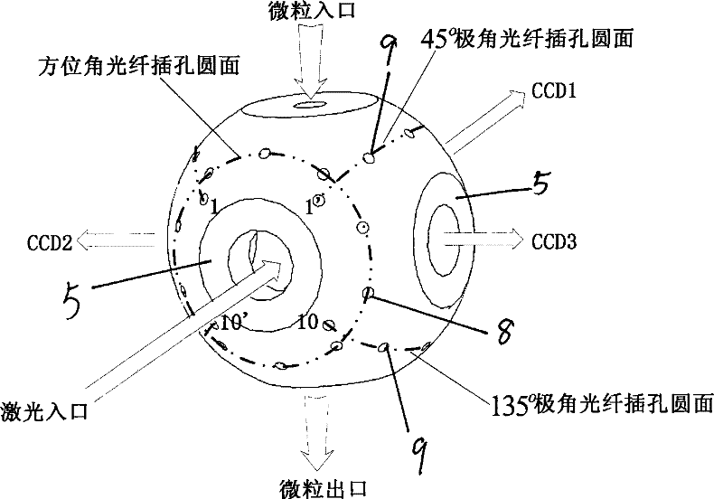
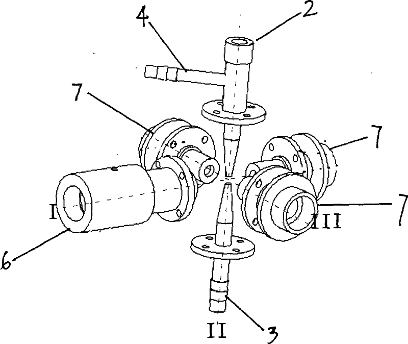
[0028] The device for monitoring the shape and scattering of microparticles based on images is characterized in that it includes a spherical scattering cavity 1, the inner surface of which is roughened and blackened, and the top and bottom of the scattering cavity 1 are respectively positioned on the radial line. The sample tube 2 and the outlet tube 3, the microparticle flow incident from the sample tube 2 passes through the cavity center and then enters the outlet tube 3, and the side wall of the sample tube 2 is communicated with a sheath flow tube 4, which is connected with the sample tube 2. On the radial surface of the scattering chamber 1 perpendicular to the central axis of the air outlet pipe 3, there are four installation holes 5 evenly arranged, and each installation hole 5 points to the center of the scattering chamber 1, and one of the installation holes 5 is installed with Semiconductor laser 6, microscope magnifying CCD imaging dev...


PUM


Abstract

The invention discloses a kind of instrument bases on the graphic monitoring micro-particle shape and scatter. On the scatter cavity the inner surface is roughed and black finish and the bottom side and the top side sets up the micro-particle flowing sample pipe and escape pipe. On the horizontal direction radial face of the scatter cavity installs one semiconductor laser interval 90degree and three adjustable microscope. The scatter cavity distributes forty azimuth angles directing to the cavity center and the polar angles fiber jack in regular and in the polar fiber jack installs sample fiber and it can over-all detect the micro-particle scatter signal from the forty azimuth angles and screens the single particle through the light beam by the microscope enlarge CCD imagery technology and make the shape of particle statistical and classified and general the relevance condition of the presented scatter theory meanwhile make the inversion theory modified.

Description

technical field [0001] The invention relates to the field of optics, in particular to a device for monitoring the shape and scattering of microparticles based on images. Background technique [0002] As an important parameter affecting and characterizing the physical properties of microparticles, particle shape research has received more and more attention. Compared with the relatively mature particle size measurement technology, the development of particle shape measurement lags behind, and it has not been reported in China at present. By measuring the data of particle shape, more abundant information can be provided for process dynamics research; in the production process, considering the influence of particle shape parameters can monitor product quality and reduce production costs, such as pharmaceutical, paper, cement and other industries; particle shape It can also respond to the source to a certain extent so as to effectively control pollution; the deposition position...

Claims


Application Information

Patent Timeline
Patent Type & Authority Patents(China)
IPC IPC(8): G01N15/10G01N21/53
Inventor 邵士勇姚永帮饶瑞中
Owner ANHUI INST OF OPTICS & FINE MECHANICS - CHINESE ACAD OF SCI
Learn More