High conductance cryopump for type iii gas pumping

A cryogenic pump, gas technology, applied in the direction of pump, pump test, multi-stage pump, etc., can solve the problem of increasing the speed of suction of non-condensable gas, etc.

Active Publication Date: 2007-09-26
EDWARDS VACUUM LLC
View PDF4 Cites 26 Cited by
  • Summary
  • Abstract
  • Description
  • Claims
  • Application Information

AI Technical Summary

Problems solved by technology

For example, U.S. Patent No. 4,718,241, which is hereby incorporated by reference herein, describes a design that increases the rate at which noncondensable gases are pumped, while at the same time limiting the frequency of renewal of the system

Method used


Image

  • High conductance cryopump for type iii gas pumping
  • High conductance cryopump for type iii gas pumping
  • High conductance cryopump for type iii gas pumping

Examples


Embodiment Construction

[0029] A description of the preferred embodiments of the invention follows:

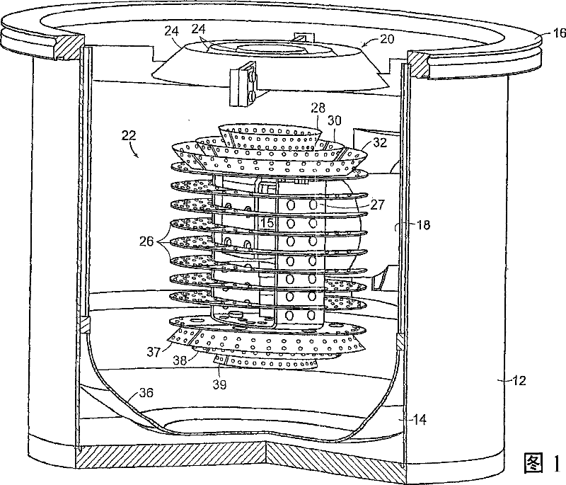
[0030] Figures 1-5 illustrate one embodiment of the present invention. Figure 1 is a perspective view of a cryopump with vacuum vessel 12 and radiation shield 14 opened. The vacuum vessel 12 may be mounted directly to the working chamber on the flange 16, or to an intermediate gate valve between the vacuum vessel and the working chamber. The cryocooler 15 of the two-stage cold finger protrudes into the housing through a side opening. In this embodiment, the second stage of the refrigerator is surrounded by a cylinder 18, wherein the cylinder 18 shields the second stage of the refrigerator. The cylinder 18 minimizes the evaporation and subsequent condensation of the gas in the cold finger, where the temperature of the cold finger fluctuates along the cold finger, as described in U.S. Patent No. 5,156,007, which Incorporated herein by reference.

[0031] The refrigerator includes a displacer in an ...


PUM


Abstract

A cryopump provides for high pumping speed of Type III gases. An open configuration of a frontal array provides high conductance of gases into a radiation shield which is shaped to focus gases toward a second stage array. The second stage array has an open configuration of baffles coated with adsorbent. Substantially all of the adsorbent has a direct line of sight to the radiation shield or to the opening in the radiation shield, and substantially all of the baffles are coated with adsorbent. In one form, the second stage cryopump array comprises an array of discs fanned to define a generally ball shaped envelope.

Description

[0001] related application [0002] This application is a continuation of, and claims the benefit of, US Application Serial No. 10 / 948,955, filed September 24, 2004. The entire teaching of this application is hereby incorporated by reference herein. Background technique [0003] Currently available cryopumps, whether open to refrigerate or closed to refrigerate, generally follow the same design philosophy. A cryogenic second stage array, typically operating in the 4-25 degree Kelvin range, is the primary pumping surface. This surface is surrounded by a high temperature cylinder, typically operating in the temperature range of 40-130 degrees Kelvin, which provides radiation shielding for the lower temperature array. Said radiation shielding generally comprises an enclosure which is closed except for the front array between the main suction surface and the chamber to be evacuated. This higher temperature, first stage, front array all act as pumping locations for higher boilin...

Claims


Application Information

Patent Timeline
Patent Type & Authority Applications(China)
IPC IPC(8): F04B37/08F04B37/02
CPCF04B37/08F04B37/02F04B37/04Y02E60/36F04B25/00F04B37/085F04B2205/065F04B2205/112F05B2220/61F25B9/14Y10S417/901
Inventor 阿伦·J·巴特莱特约翰·诺德博格布赖恩·汤普森
Owner EDWARDS VACUUM LLC
Why Eureka
Try Eureka