Synchronous operation control system of roving frame driving mechanism

A transmission mechanism and synchronous operation technology, which is applied to spinning machines, continuous winding spinning machines, textiles and papermaking, etc., can solve the problem of unsatisfactory synchronous operation of the transmission mechanism of the roving frame, complicated control circuits, poor operation stability, etc. problems, to achieve the effect of improving synchronous operation performance, stable and accurate control process, stable and reliable operation

Inactive Publication Date: 2009-07-29
北京联泽工业控制有限责任公司
View PDF3 Cites 0 Cited by
  • Summary
  • Abstract
  • Description
  • Claims
  • Application Information

AI Technical Summary

Problems solved by technology

However, the electrical control of this type of transmission mechanism is still accustomed to adopting ordinary electrical components and circuit control methods, which has poor operating stability, high failure rate, and complicated control circuits, which makes the synchronous operation of the transmission mechanism of the roving frame unsatisfactory and cannot be improved. Fully adapt to the needs of the development of roving frame technology

Method used


Image

  • Synchronous operation control system of roving frame driving mechanism
  • Synchronous operation control system of roving frame driving mechanism

Examples


Embodiment Construction

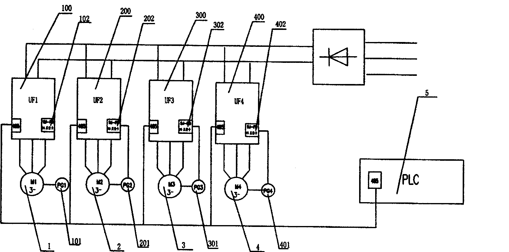
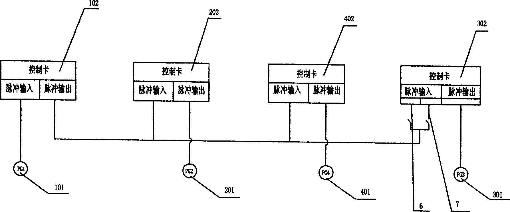
[0014] combined reference figure 1 , figure 2 , a synchronous operation control system of a roving frame transmission mechanism, in the transmission mechanism, the flyer rotating motor 1 is used as the main motor, and the bobbin winding motor 2, the tendon lifting motor 3 and the roller drafting motor 4 are all used as the slave motors. The frequency converter 100 configured with the main motor 1 is used as the main frequency converter, the frequency converter 200 configured with the bobbin winding motor 2, the frequency converter 300 configured with the tendon lifting motor 3 and the frequency converter 400 configured with the roller drafting motor 4 are all used as slave frequency converters device. The above-mentioned master-slave motors are all equipped with encoders for real-time detection of the motor speed and outputting corresponding pulse signals, wherein the encoder 101 configured by the master motor 1 is used as the master encoder, and the encoder 201 configured b...


PUM


Abstract

The invention discloses a flyer frame driving gear synchronous operation control system. It includes flyer, spindle bearing plate, bobbin, and roller electric machine. Each of the electric machines is set frequency converter and encoder. The flyer electric machine is used as the driving electric machine. Others are driven. The frequency converter set in driving electric machine is driving. Others are driven. The encoder is also as the same. The driving encoder is accessed to driving frequency converter synchronization control card and input interface of each driven. Each of the driven encoder is accessed to driven frequency converter synchronization control card. Programmable controller is set to connect to the driving and driven frequency converter. It has extract control, reliable working, and can improve synchronous operation performance of the driving gear.

Description

technical field [0001] The invention relates to a transmission mechanism of a roving frame, in particular to an electrical control system for synchronous operation of the transmission mechanism. Background technique [0002] The transmission mechanism of the roving frame in the prior art, one technical method is to use an electric motor as the power source, and realize the four major movements of bobbin winding, flyer rotation, roller rotation and dragon tendon lifting through the corresponding matching transmission line. The electrical control is relatively simple, but its mechanical structure is complicated, and its synchronization and commutation are poor, which is not conducive to operation and maintenance, and has been gradually eliminated. Another technical method is that it is equipped with four variable frequency motors, and each variable frequency motor drives and controls one of the four major movements of bobbin winding, flyer rotation, roller rotation and dragon ...

Claims


Application Information

Patent Timeline
Patent Type & Authority Patents(China)
IPC IPC(8): D01H1/20
Inventor 王成吉管阳春李建霞
Owner 北京联泽工业控制有限责任公司
Why Eureka
Try Eureka