
Link load sharing method and relay device

A technology of forwarding equipment and link load, applied in the field of data communication, which can solve problems such as non-working, waste of limited bandwidth resources, link blocking, etc.

Active Publication Date: 2009-01-07
NEW H3C TECH CO LTD
View PDF5 Cites 0 Cited by
  • Summary
  • Abstract
  • Description
  • Claims
  • Application Information

AI Technical Summary

Problems solved by technology

However, only one link is in working state at any time, and the other link is in blocked state and does not work, resulting in a large waste of limited bandwidth resources

Method used


Image

  • Link load sharing method and relay device
  • Link load sharing method and relay device
  • Link load sharing method and relay device

Examples


Embodiment Construction

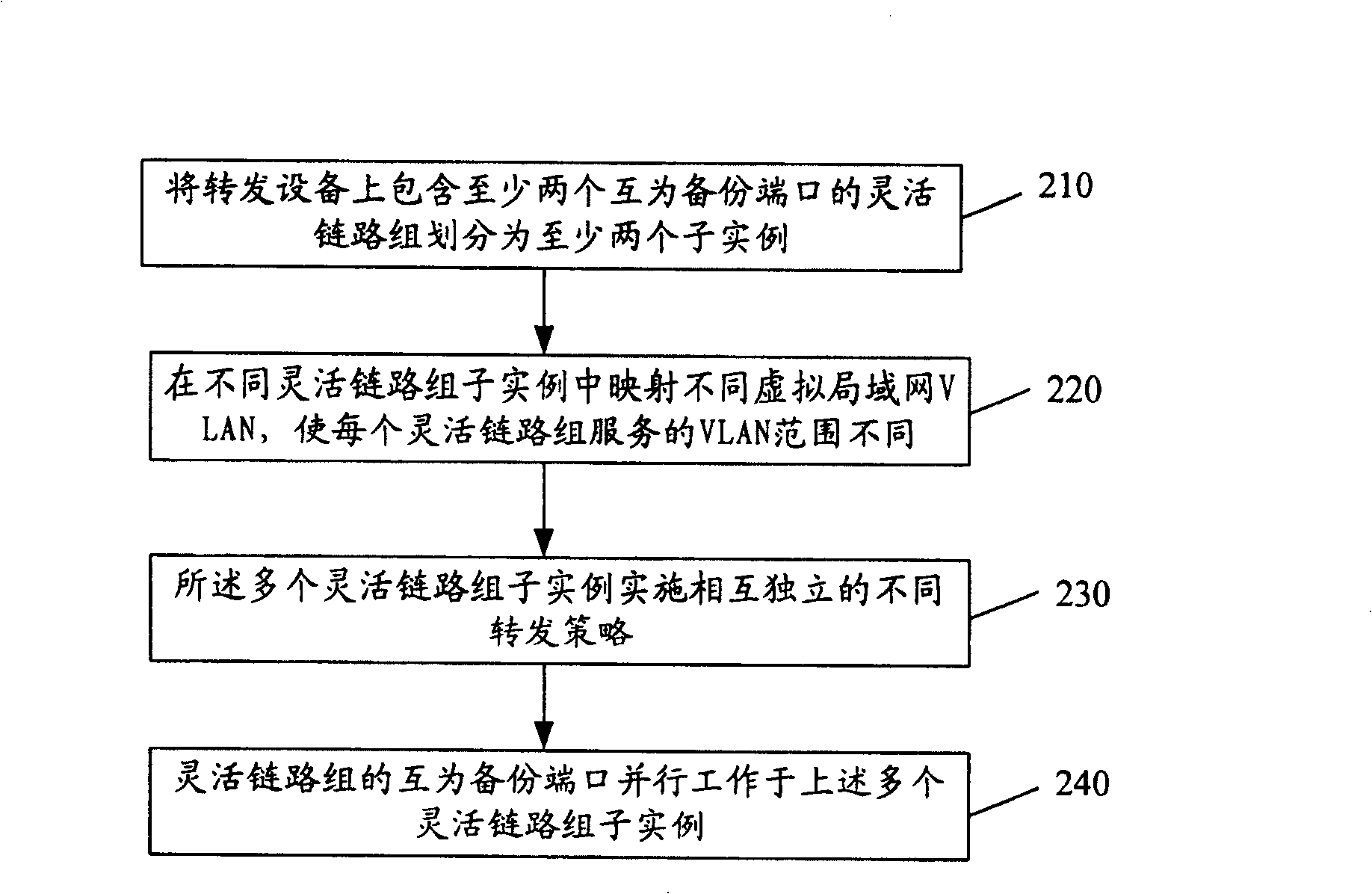
[0026] see figure 2 , which is a flowchart of an embodiment of a method for link load sharing in the present invention.

[0027] Step 210: Divide the flexible link group including at least two mutually backup ports on the forwarding device into at least two sub-instances. First, ports in a smart link group (Smart Link) need to be determined. Usually, multiple uplink ports of a forwarding device are used as a smart link group. The links of the ports belonging to a flexible link group are mutual backup links, so the ports are also considered as mutual backup ports. One flexible link group can be configured for multiple ports on a forwarding device, or multiple flexible link groups can be configured, as long as a port only belongs to one flexible link group. Secondly, each flexible link group is divided into multiple flexible link group sub-instances, and it should be noted that the ports included in each flexible link group sub-instance are still all original ports of the fle...


PUM


Abstract

The invention discloses a link load sharing method, where the links of plural ports on a transmitter are backups, mutually, and plural links can be in working state at the same time but serve different objects. And it also discloses a transmitter, comprising configuration unit, sub-instance dividing unit and central transmitting unit. Thus, plural links can work at the same time, avoiding bandwidth waste.

Description

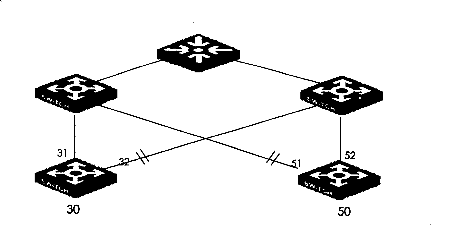
technical field [0001] The invention relates to the field of data communication, in particular to a link load sharing method and a forwarding device method. Background technique [0002] In current networks with high reliability requirements such as operators, dual uplink networking is one of the commonly used application networking methods. When the primary link fails, the traffic is switched to the backup link. In the network layer, the links located close to the edge layer devices are generally referred to as uplinks, and the links near the core layer devices are referred to as downlinks. Please refer to figure 1 , which is a schematic diagram of an existing dual uplink networking. [0003] In the figure, the switching device 30 is a device close to the edge layer, and the link where the port 31 is located and the link where the port 32 is located are dual uplinks. Wherein, the link where the port 31 is located is the active link, and the link where the port 32 is locat...

Claims


Application Information

Patent Timeline
Patent Type & Authority Patents(China)
IPC IPC(8): H04L12/24H04B1/74H04L1/22H04L12/26
Inventor 周万徐鹏飞
Owner NEW H3C TECH CO LTD
Learn More