
Swing-head spanner push-button structure

A head swing and pivot swing technology is applied in the field of the toggle structure of swing head wrenches, and can solve the problems of impractical design, obstacles to pivot swing between swing head 2 and handle 1, and unsuitable industrial utilization.

Active Publication Date: 2008-10-29
胡厚飞
View PDF5 Cites 0 Cited by
  • Summary
  • Abstract
  • Description
  • Claims
  • Application Information

AI Technical Summary

Problems solved by technology

[0003] The existing structure still has many disadvantages in practice. Please refer to FIG. 9 and FIG. 10 . It is toward the handle 1, and the toggle part 6 facing the handle 1 will protrude from the periphery of the swing head 2, and the toggle part 6 protruding from the swing head 2 will cause the swing head 2 and The pivoting obstacle between the handles 1 requires a clear space to rotate when the two ears 4 protruding from one end of the handle 1 pivot relative to the swing head 2, and the protruding toggle The part 6 will block the ear part 4 of the handle 1, so that the handle 1 cannot pivot to the angle to be used, and of course the pulling work cannot be performed. This kind of design that does not meet the industrial utilization is very impractical, so there is an improvement the necessity of

Method used


Image

  • Swing-head spanner push-button structure
  • Swing-head spanner push-button structure
  • Swing-head spanner push-button structure

Examples


Embodiment Construction

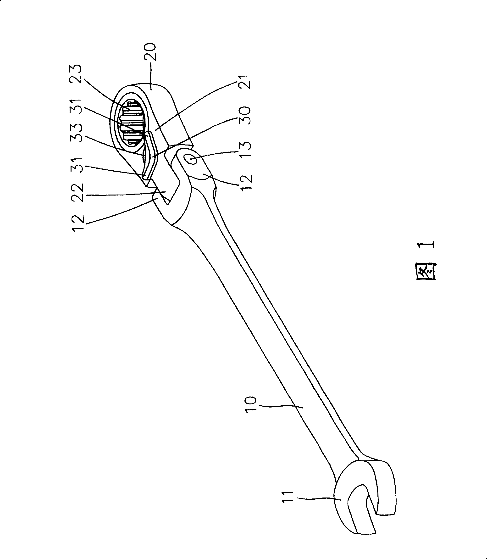
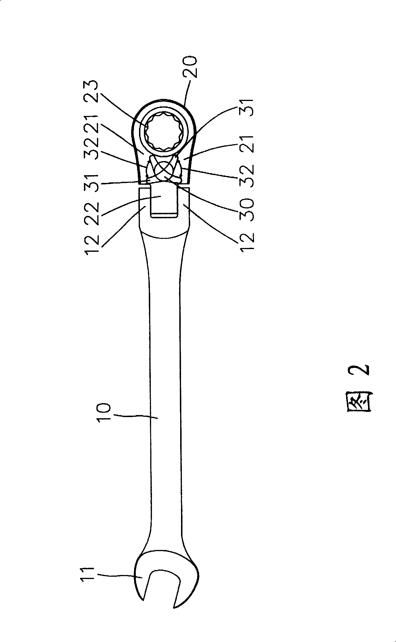
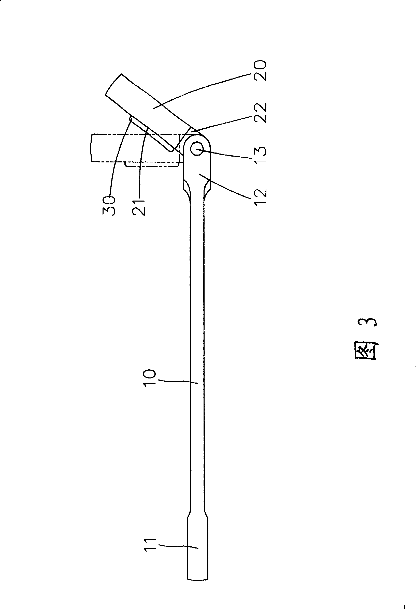
[0021] Referring to FIG. 1 and FIG. 2 , the present invention includes a handle 10 , a swing head 20 pivotally arranged at one end of the handle 10 , and a toggle button 30 pivotally arranged at one side of the swing head 20 . The toggle button 30 extends with a toggle portion 31 on both sides respectively, and the toggle portion 31 can control the rotation direction of the driving portion 23 of the swing head 20 without causing pivoting between the handle 10 and the swing head 20 obstacles; of which:

[0022] The handle 10 includes a first end and a second end, the first end has a trigger portion 11, the second end is provided with a pivot portion 12, and the pivot portion 12 is pierced with a pivot member 13 .

[0023] The swing head 20 is pivotally disposed on the second end of the handle 10 . The swing head 20 has a first end and a second end, and a belly region 21 is formed in the middle. The first end of the swing head 20 is provided with a pivot portion 22, the pivot ...


PUM


Abstract

A swing-head spanner push-button structure includes a handle, a swing head, and a push button. The handle includes a first end and a second end, wherein a spanner part is provided at the first end, and a pivot part is provided at the second end. The swing-head is pivotally fixed at the second end of the handle so as to generate relate pivot-swing relation. The swing-head includes a first end and a second end between which forms an abdominal region. A pivot link part pivot fixed on the handle pivot part is provided at the first end of the swing head, and a driving part is provided at the second end. The push button is pivotally fixed in the abdominal region of the swing head to generate relate pivot-swing motion. The push button respectively has one shifting part extending by two sides thereof which has an amplitude of swing toward two sides of the swing-head and the driving part thereof. By this progressive invention, a user has a convenient push button operating space in the short abdominal region, and the turning direction of the swing head driving part is controlled without being intervened by the push button at the time of the handle changing angle relative to the swing head.

Description

technical field [0001] The invention relates to a wrench toggle structure, in particular to a toggle structure applied to an oscillating head wrench. Background technique [0002] Please refer to FIG. 7 and FIG. 8 , which show the structure of the existing swing head wrench, which mainly includes a handle 1 , a swing head 2 pivotally mounted on the handle 1 , and a toggle button 3 disposed on the swing head 2 . One end of the handle 1 has two protruding ear portions 4, one end of the swing head 2 is pivotally arranged on the two ear portions 4 of the handle 1, so as to produce a relative pivoting movement, and the other end of the swing head 2 A driving part 5 is then provided, and the toggle button 3 is pivotally arranged on one side of the swing head 2, and can control the rotation direction of the driving part 5, and the toggle button 3 is respectively extended from two sides with toggle parts. 6. It can be operated by the user to control the rotation direction of the dr...

Claims


Application Information

Patent Timeline
Patent Type & Authority Patents(China)
IPC IPC(8): B25B23/00B25G3/26B25G3/38
Inventor 胡厚飞
Owner 胡厚飞
Learn More