
Refrigeration system control equipment and its control method

A technology of refrigeration system and control equipment, applied in the direction of refrigerator, pump control, refrigeration components, etc., can solve the problems of unsuitable replacement, damage and loss of valuables, etc.

Active Publication Date: 2008-07-23
QINGDAO HAIER BIOMEDICAL TECH CO LTD
View PDF8 Cites 0 Cited by
  • Summary
  • Abstract
  • Description
  • Claims
  • Application Information

AI Technical Summary

Problems solved by technology

If the compressor starts and stops once every 10 minutes, the calculated service life of the relay is about 1.9 years, which is much lower than the 8-10 years service life of other components of the refrigeration equipment
At the same time, since this kind of relay is generally integrated with the electronic controller on a circuit board, it is not suitable to be replaced. Therefore, the relay reduces the service life of the entire electronic controller and increases the operating cost of the refrigeration system.
More importantly, after the electronic controller fails, if it cannot be repaired in time, the refrigeration system may not be able to resume work in time, causing damage to the valuables stored in it and causing losses.

Method used


Image

  • Refrigeration system control equipment and its control method
  • Refrigeration system control equipment and its control method

Examples


Embodiment Construction

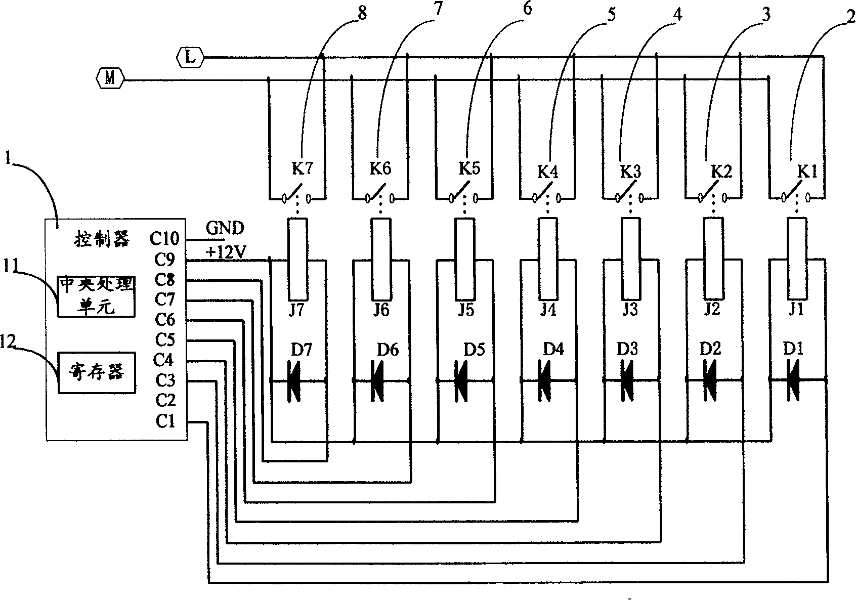
[0027] Please see figure 1 , is a schematic diagram of the first embodiment of the present invention. This figure shows a schematic circuit diagram of the refrigeration system control device of the present invention. Only the parts relevant to the present invention are shown in the figure.

[0028] figure 1 The refrigeration system control equipment circuit in the circuit includes a controller 1, a relay 2 to a relay 8. Wherein, the controller 1 is a core unit for controlling the refrigeration system, including a central processing unit 11 and a register unit 12, and the register unit 12 includes several independent registers. The controller 1 can read the temperature range set by the user and receive the system temperature obtained by the temperature measuring element. According to the above parameters, the controller 1 makes a judgment on whether to start the compressor, and according to the judgment result, the output connected to the relay The contact outputs the compr...


PUM


Abstract

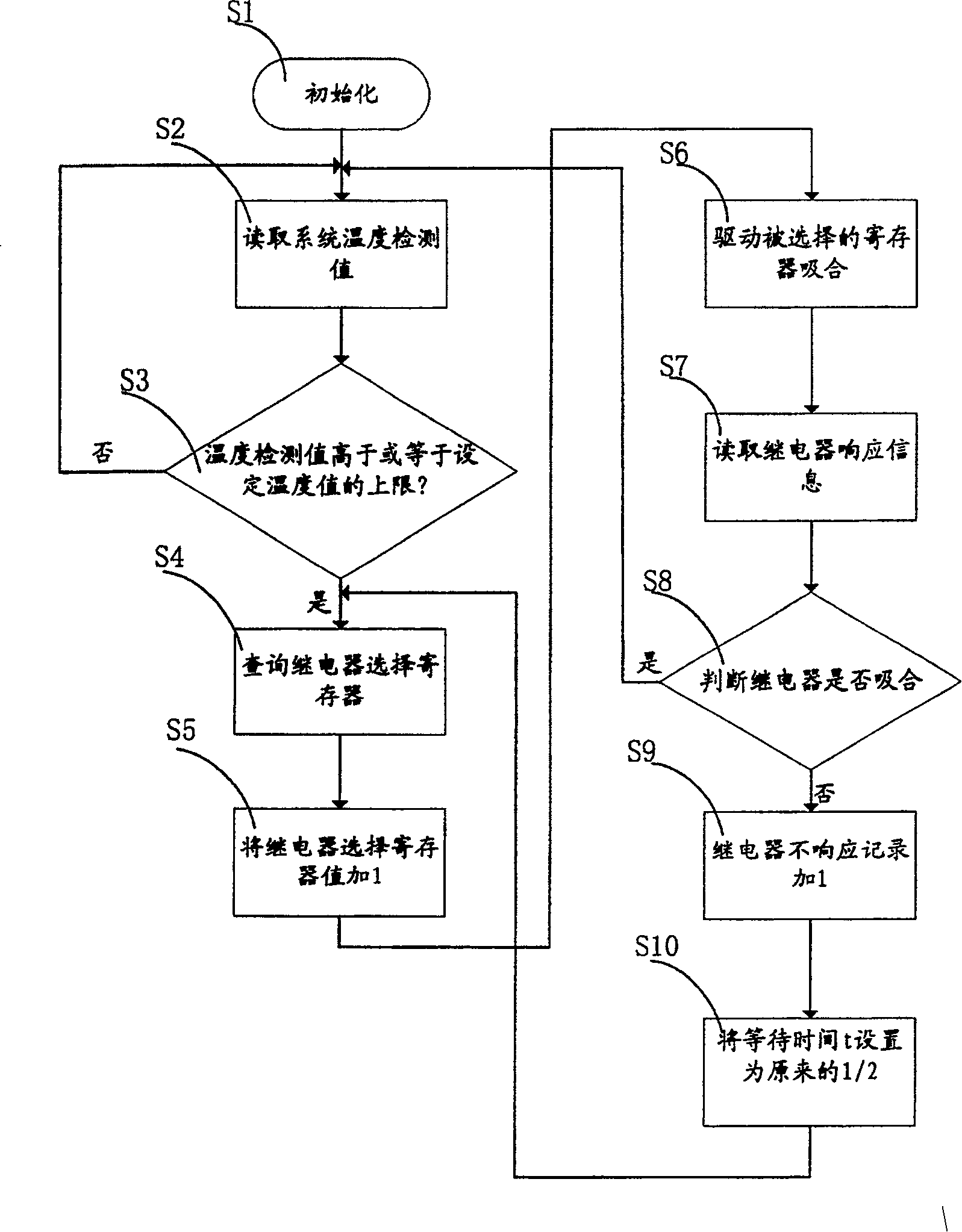
A method for controlling refrigeration system includes fetching detection value of system temperature, comparing said detection value with preset temperature range, outputting start-up signal of compressor through output contact connected with relay when detection value is greater than top limitation of preset temperature range then returning to step of fetching detection value. The control device used for realizing said method is also disclosed.

Description

technical field [0001] The invention relates to a refrigeration system, in particular to a control device for the refrigeration system. The invention also simultaneously provides a control method applied to the control device. Background technique [0002] In some special-purpose refrigeration systems, the control range of the system temperature is extremely strict. For example: the temperature inside the blood storage box needs to be controlled at 4±1°C. If the temperature leaves this range, the blood may lose its medical value very quickly. [0003] At present, the method for realizing the above-mentioned temperature control in the refrigeration system is to frequently start and stop the compressor. When the temperature in the box is close to the upper limit of the temperature, immediately start the compressor to cool down; when the system temperature is close to the lower limit of the control temperature after the compressor has been running for a certain period of time...

Claims


Application Information

Patent Timeline
Patent Type & Authority Patents(China)
IPC IPC(8): F25B49/02F04B49/06
Inventor 刘占杰白文涛牛愉涛郑玲
Owner QINGDAO HAIER BIOMEDICAL TECH CO LTD
Learn More