Double-wire terminal box

A junction box and line type technology, applied in the field of junction boxes, can solve problems such as poor operability

Inactive Publication Date: 2008-05-14
AIOI SYSTKK
View PDF5 Cites 0 Cited by
  • Summary
  • Abstract
  • Description
  • Claims
  • Application Information

AI Technical Summary

Problems solved by technology

With this structure, great force is required to remove the display unit from the wiring guide base, which results in poor operability when replacing the unit

Method used


Image

  • Double-wire terminal box
  • Double-wire terminal box
  • Double-wire terminal box

Examples


Embodiment Construction

[0033] Preferred embodiments of the present invention will now be described in detail with reference to the accompanying drawings. It should be noted that the present embodiment will be described for a game device in which the image processing device of the present invention is equipped.

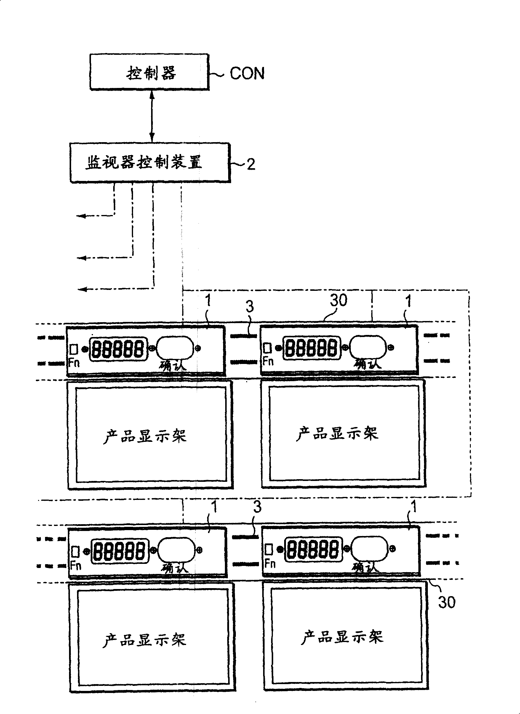
[0034]In the following description, the present invention will be discussed in connection with the case of a two-wire type junction box where the present invention is applied in the wiring of a remote control system for remotely managing merchandise displayed on a product display rack.

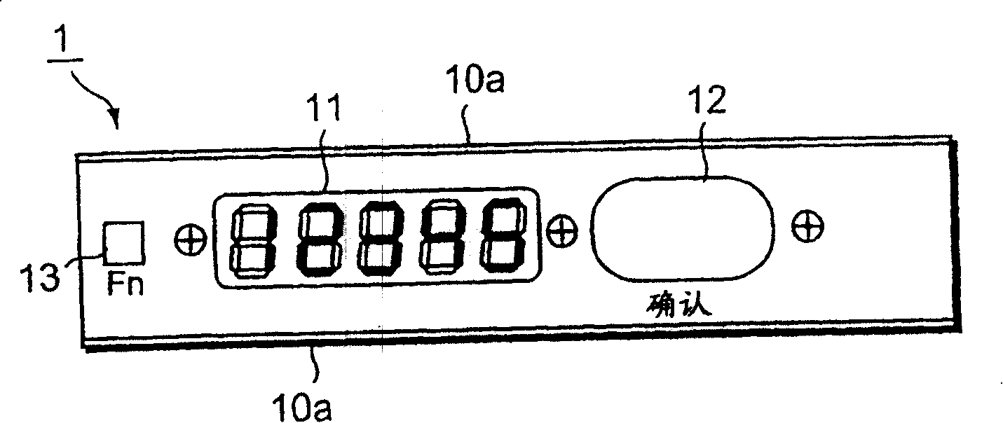
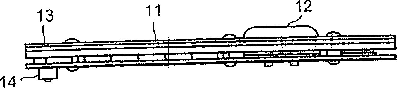
[0035] figure 1 The overall structure of the remote control system applying the present invention is shown. In this remote control system, a plurality of display devices 1 (each of which is an example of a device to be controlled) and a monitor control device 2 (which is an example of a control device) are provided so that they are connected via two power lines 3. Transmission / reception power and data comm...


PUM


Abstract

The present invention relates to a joint-box with removable display device for displaying and presetting data created by control device and contents of power transmit-receiving communication. It the display device a pair of wiring components is mounted, and the top portion of said wiring component is toward the joint-box and bottom surface, and every top end portion is equipped with a contact, and the portion of said joint-box which is opposite to bottom surface portion has an opening, and the end portion of every side wall of the long-strip box is formed into thrust portion.

Description

[0001] This application is based on and claims priority to prior Japanese Patent Application No. 2000-206820 filed on July 7, 2000. (1) Technical field [0002] The invention relates to a junction box for installing multiple receiving devices (controlled devices), so that each device can establish data and power communication with a sending device (controlling device) through two power lines. (2) Background technology [0003] Conventionally, a two-wire type data and power transmission / reception communication system is known as a technique for realizing data and power transmission / reception communication using two power lines (i.e., simultaneous power (electricity) transmission / reception and data communication technology) see Japanese Patent 27887976). In this system, one transmitter-side device and multiple receiver-side devices are connected together with two power cables. Power charging and data decoding are performed on the receiver device side while power containing da...

Claims


Application Information

Patent Timeline
Patent Type & Authority Patents(China)
IPC IPC(8): H02G3/16
Inventor 多田洁
Owner AIOI SYSTKK
Why Eureka
Try Eureka