Batting tee

a technology of batting tee and bat, which is applied in the field of batting tee, can solve the problems of time-consuming recovery process, short practice time, and tiring for the practicing batter, and achieve the effect of improving hand/eye coordination

Active Publication Date: 2018-03-13
LEE DONALD M
View PDF25 Cites 4 Cited by
  • Summary
  • Abstract
  • Description
  • Claims
  • Application Information

AI Technical Summary

Benefits of technology

[0011]It is another object of the present invention to provide a batting tee that permits the practicing batter to practice in a confined area without the need for a net or a screen since the strike target (i.e. the ball) does leave the team upon receiving a strike from the bat.
[0012]Another object of the present invention is to damp at least the return of the strike target to its standby position to allow time for the batter to reset his / her batting stance to be ready for the next swing. The return of the tee to its upright position can be used as a timing mechanism. The controlled slow return of the tee will allow only brief periods (approximately 1-6 seconds) in between bat swings, which may improve hand / eye coordination.

Problems solved by technology

The recovery process is time consuming, tiring, and, unlike batting, “boring” for the practicing batter.
Thus, it has been observed that a young batter who is practicing alone, tends to cut his practice short when ball recovery after every hit is necessary.

Method used


Image

  • Batting tee
  • Batting tee
  • Batting tee

Examples


first embodiment

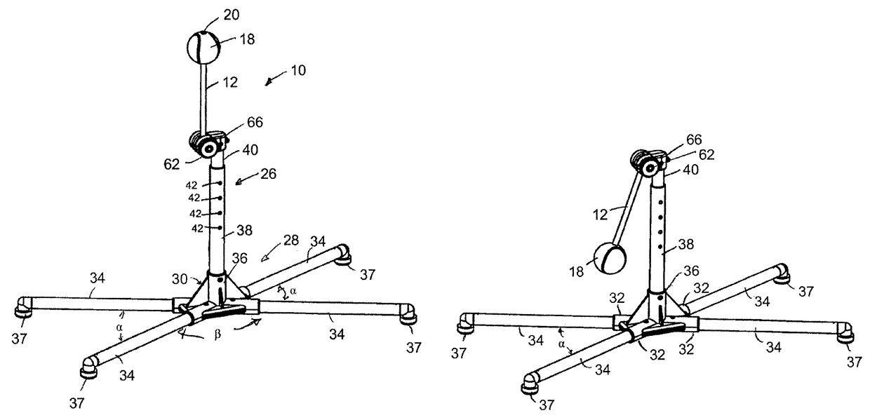
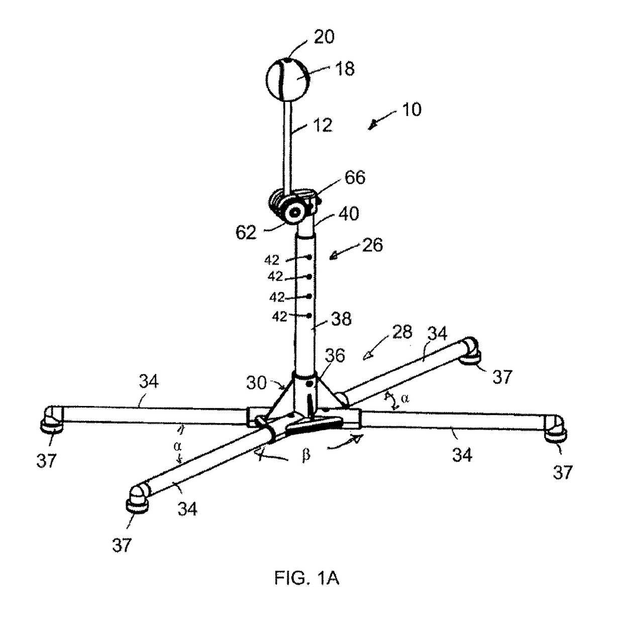
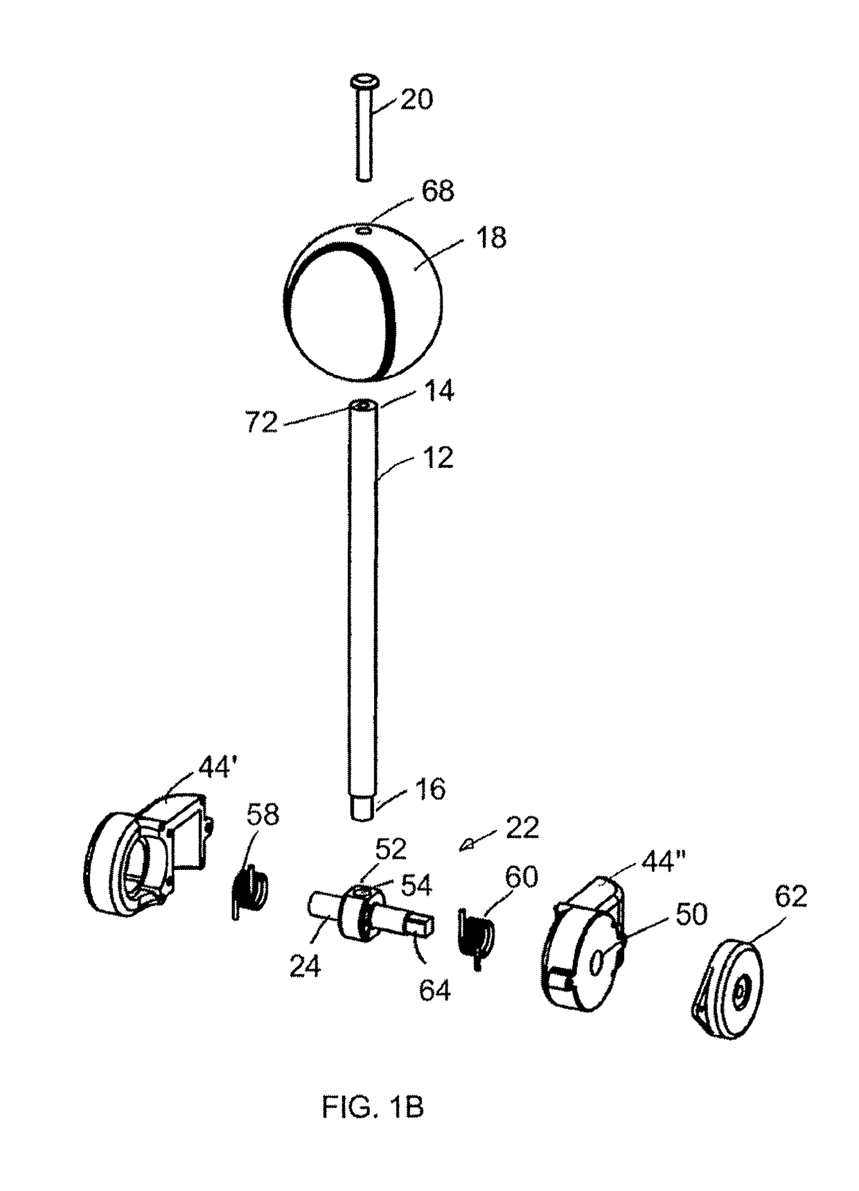
[0041]Referring to FIGS. 1A and 1B, a batting tee 10 according to the present invention includes a swing arm 12 having a distal end 14, and a proximal end 16. A strike target 18 is attached / connected to the distal end 14 of the swing arm 12. The strike target 18 may be a baseball, a softball or any other ball.

[0042]The strike target 18 may be integrated with the distal end 14 of swing arm 12 or may be re-attachably detachable (reconnectably disconnectable) from the distal end 14 of the swing arm 12. For example, the strike target 18 may be connected to the distal end 14 of the swing arm 12 with a screw 20 or the like fastener.

[0043]A batting tee according to the present invention includes a damped return mechanism 22. The damped return mechanism 22 includes a rotatable axle 24 (see FIGS. 1B and 1D). The proximal end 16 of the swing arm 12 is integrated with the rotatable axle 24, permitting the swing arm 12 to swing about the longitudinal axis of the rotatable axle 24, i.e. the rota...

second embodiment

[0072]Referring to FIG. 23, the proximal end 16 of the swing arm 12 is connected to a damped, spring-loaded, return mechanism 22. The return mechanism 22 in the second embodiment also includes a damper 62 (FIG. 2C), which may be a rotary or a torque damper connected to an axle 25 (FIG. 2D).

[0073]Referring to FIGS. 2D and 2E, the axle 25 is rotatably mounted to and supported by a support bracket 74. A double torsion spring 76 having two spring portions 78 is provided as the mechanical energy storage device. The axle 24 is received inside of the spring portions 78. Two free ends 80 of the spring 76 are connected to a rotatable swing pole 82, while a connecting portion 84 of spring 76 is biased against a plate 86.

[0074]The swing pole 82 includes a cylindrical receptacle portion 88 that receives a proximal end portion of the telescopic swing arm 12 and is fixed thereto preferably with a releasable device or a screw to permit selective assembly and disassembly of the swing arm 12. The sw...


PUM


Abstract

A batting tee that includes a return mechanism, a swing arm connected to the return mechanism to swing about a rotation axis, a strike target connected to the swing arm, and a base supporting the return mechanism and the swing arm, the return mechanism including a mechanical energy storage device that stores mechanical energy when the swing arm swings in one direction in response to a batter's striking of the strike target, and a damper that slows down the swinging of the swing arm in the opposite direction as the swing arm swings back by the force supplied by the mechanical energy storage device.

Description

CLAIM OF PRIORITY[0001]The present application claims priority to U.S. Provisional Application Ser. No. 62 / 142,035, filed Apr. 2, 2015, entitled Pivoting Baseball / Softball Tee with Slow Return Mechanism, which is hereby incorporated by reference.FIELD OF THE INVENTION[0002]The present invention relates to a batting tee, and in particular to a batting tee with a swing arm and an automatic and damped return mechanism.BACKGROUND OF THE INVENTION[0003]A typical batting tee includes a base, and an elongated stand attached to the base, which includes a cradle or the like feature for receiving a ball, such as a baseball or a softball.[0004]In order to practice batting, a ball is placed in the cradle for the batter to hit with a bat. Thereafter, another ball could be placed in the cradle for another hit, or the same ball could be recovered and placed in the cradle for another hit if only one ball is available, for example.[0005]To recover the ball, a batter who is practicing alone, would ha...

Claims


Application Information

Patent Timeline
Patent Type & Authority Patents(United States)
IPC IPC(8): A63B69/00A63B71/02
CPCA63B69/0002A63B69/0091A63B69/002A63B69/0075A63B2225/093A63B2069/0008A63B2071/026A63B2208/0204A63B2210/50A63B69/0079
Inventor LEE, DONALD M.
Owner LEE DONALD M
Why Eureka
Try Eureka