
Pantleg holding mechanism for knee pads

a knee pad and holding mechanism technology, applied in the field of pants, can solve the problems of chronic pain and/or permanent knee injury, difficult to reach, and workers to spend a substantial amount of time on their knees

Active Publication Date: 2017-05-23
5 SEAS ENG & TRADING
View PDF51 Cites 6 Cited by
  • Summary
  • Abstract
  • Description
  • Claims
  • Application Information

AI Technical Summary

Benefits of technology

The present invention is about a knee pad holder that can hold a knee pad in place on a pantleg. It is designed for individuals who spend a lot of time on their knees, especially in trade and laborer industries or certain military applications. The holder has a pocket made of fabric material into which the knee pad can be inserted and secured with fastening straps. The straps are held in place on the pantleg with holding means. The invention can also be used for holding an elbow pad on a shirt sleeve or other garment. Overall, the invention provides a comfortable and stable position for knee pads or elbow pads during work activities.

Problems solved by technology

Construction workers, mechanics, repairmen, plumbers, electricians, cleaning staff and other types of workers participate in a substantial amount of physical labor due to the nature of their respective jobs and much of this work requires the worker to spend a substantial amount of time on their knees.
Crouching on one's knees is a common practice in such fields due to the nature of specific jobs and because such a position provides workers with access to a particular job location or to various things which require their attention but are difficult to reach in an upright or seated position.
Frequently applying pressure to one's knees in this manner oftentimes results in chronic pain and / or permanent knee injury.
Oftentimes knee pads fail to stay properly positioned directly over the knees, frequently moving around or sliding down the worker's leg as the wearer moves or shifts on their knees from one location to another during the course of their work.

Method used


Image

  • Pantleg holding mechanism for knee pads
  • Pantleg holding mechanism for knee pads
  • Pantleg holding mechanism for knee pads

Examples


Embodiment Construction

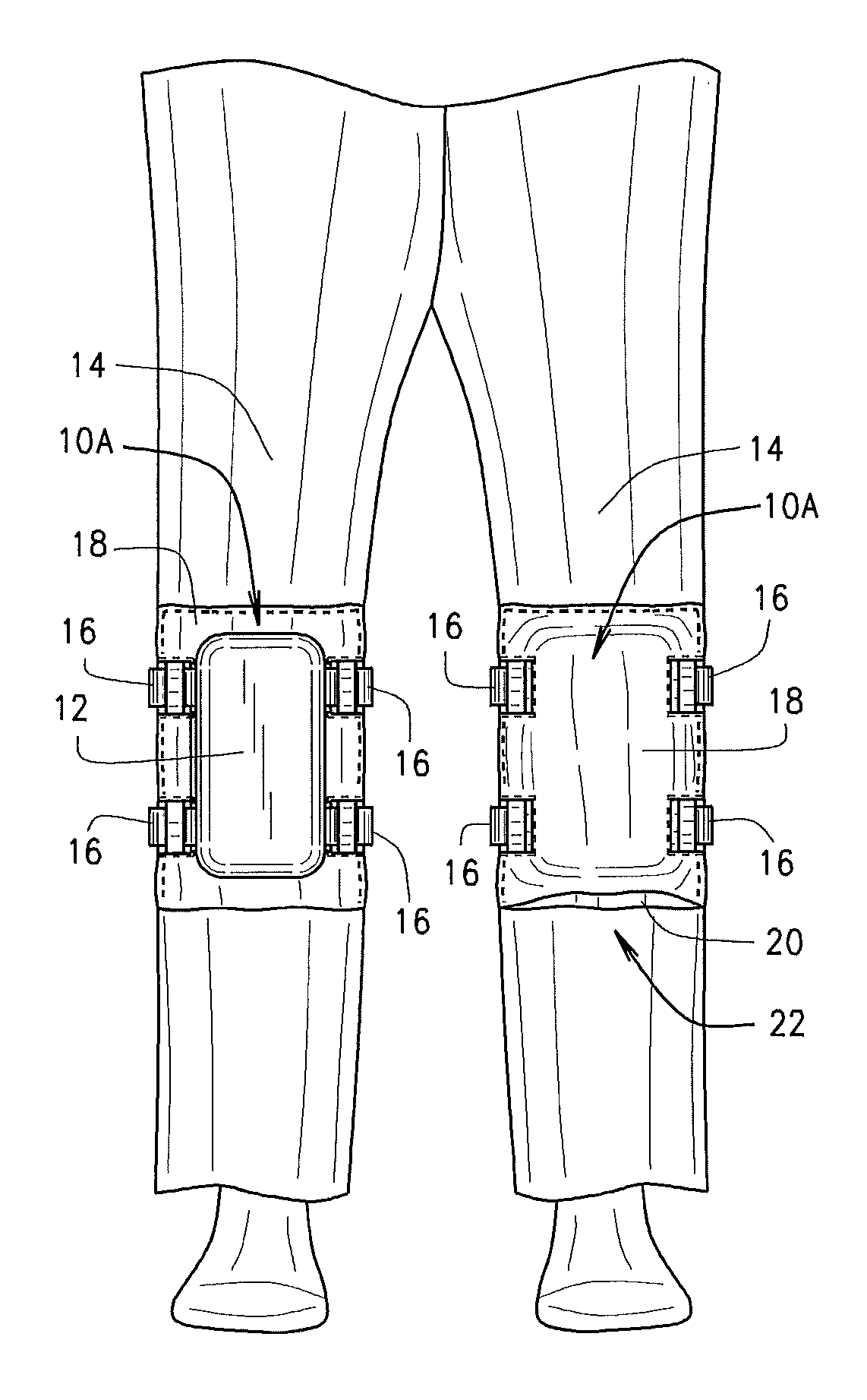
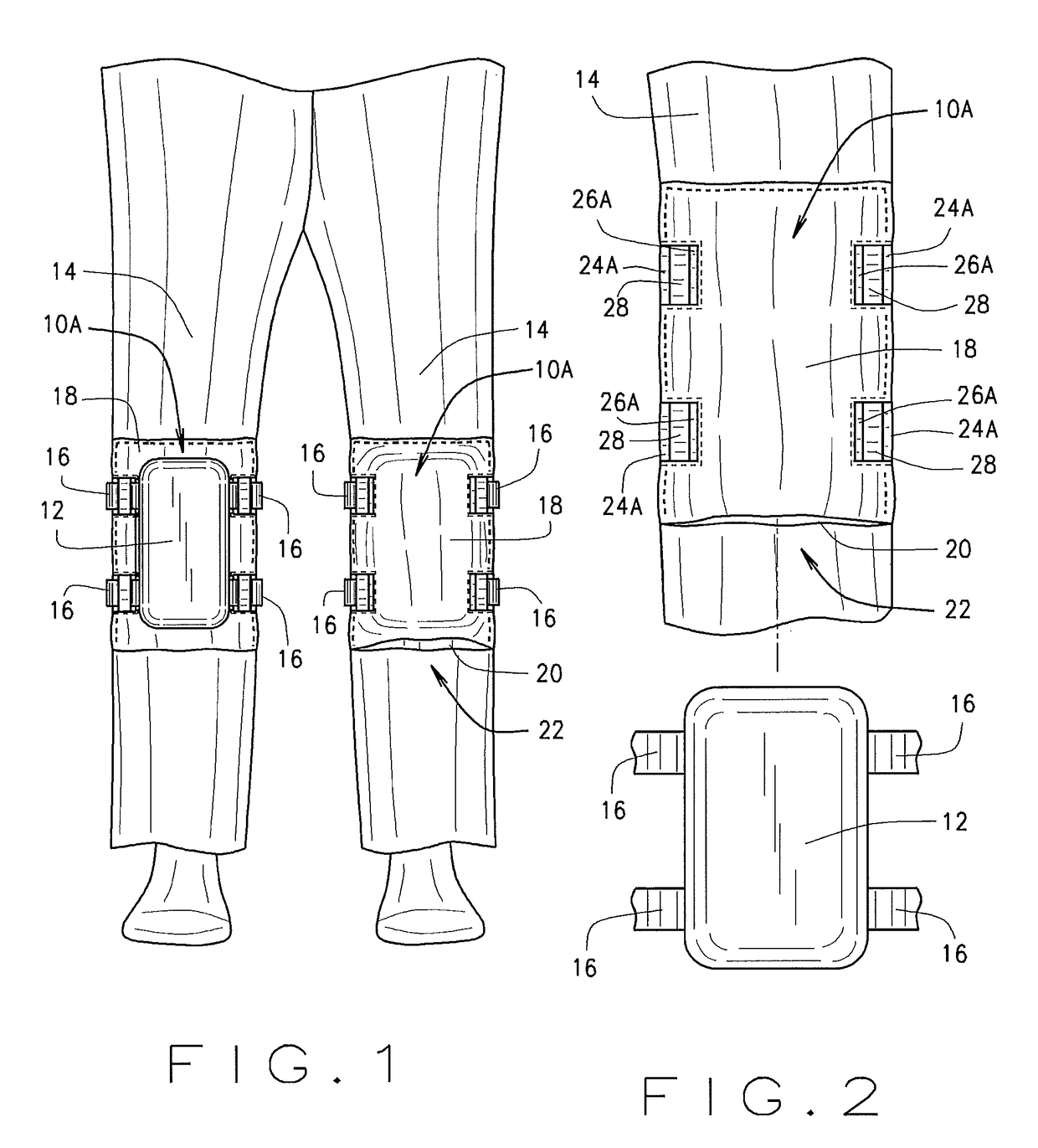
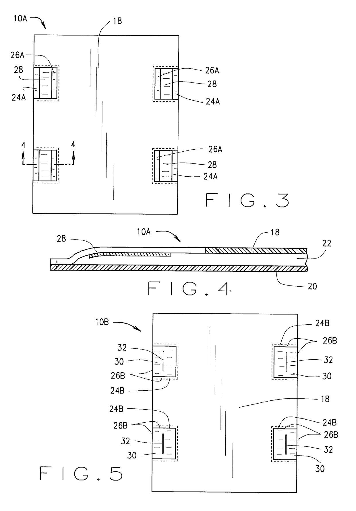
[0018]Referring now to the drawings more particularly by reference numbers, FIG. 1 illustrates one embodiment of a knee pad holding mechanism 10A which is designed for securing a knee pad 12 to a pantleg 14 and positioning it substantially over the knee region of the garment, the present mechanism 10A minimizing movement of the knee pad 12 while the wearer moves during the course of his / her work activities as will be hereinafter further explained. The mechanism 10A is designed for individuals who are required to spend a great deal of time on their knees due to the nature of their trade and is constructed such that the knee pad 12 may be removably attached to a pantleg 14 as needed. The mechanism 10A cooperates with the fastening straps 16 associated with the knee pad 12 to properly position the knee pad 12 relative to the pantleg 14. Although the present mechanisms will be described in connection with one embodiment of a typical knee pad 12, it is likewise well-suited for use with e...


PUM


Abstract

A knee pad holding mechanism for holding a knee pad over the knee region of a pantleg having a first length of fabric material and a second length of fabric material operatively secured together to form a pocket, the pocket being sized and shaped to receive a knee pad and having at least one opening located along each of the outside edges of the pocket for receiving a strap associated with the knee pad. In one embodiment, the first length of fabric material can be secured directly to the knee region of a pantleg wherein the pantleg forms the second length of fabric material. Other embodiments include using a loop, eyelet, slits or an additional section of fabric having a slit associated therewith for receiving a strap associated with the knee pad. The present mechanism is also adaptable for use to receive an elbow pad.

Description

BACKGROUND OF THE INVENTION[0001]The present invention relates generally to clothing and, more particularly, to a pantleg holding mechanism for securing a knee pad to a pantleg or other portion of a garment.[0002]Construction workers, mechanics, repairmen, plumbers, electricians, cleaning staff and other types of workers participate in a substantial amount of physical labor due to the nature of their respective jobs and much of this work requires the worker to spend a substantial amount of time on their knees. Crouching on one's knees is a common practice in such fields due to the nature of specific jobs and because such a position provides workers with access to a particular job location or to various things which require their attention but are difficult to reach in an upright or seated position. Frequently applying pressure to one's knees in this manner oftentimes results in chronic pain and / or permanent knee injury. To alleviate this type of pressure on one's knees, laborers oft...

Claims


Application Information

Patent Timeline
Patent Type & Authority Patents(United States)
IPC IPC(8): A41D13/05A41D13/06
CPCA41D13/0568A41D13/0575A41D13/065A41D13/08A41D2600/20
Inventor CARVER, JOHN W.ERICSON, KEITH
Owner 5 SEAS ENG & TRADING
Learn More