
System and method for power management of pumping system

a pumping system and power management technology, applied in the direction of motor parameters, non-positive displacement fluid engines, borehole/well accessories, etc., can solve the problems of reducing fuel consumption and emissions, blending natural gas and diesel fuel together, and reducing the efficiency of pumping engines

Active Publication Date: 2017-05-02
HYDRIL USA DISTRIBUTION LLC
View PDF13 Cites 126 Cited by
  • Summary
  • Abstract
  • Description
  • Claims
  • Application Information

AI Technical Summary

Benefits of technology

The patent text describes a method, system, and computer-readable medium for generating an operating set-point for a pumping system that includes at least one pump-unit powered by at least one generator-unit. The method involves receiving a pressure profile and pump-unit and generator-unit parameters, and generating an operating set-point based on these parameters. This operating set-point is then used to determine an input parameter for the generator-unit. The technical effect of this patent text is to provide a more efficient and effective method for generating an operating set-point for a pumping system.

Problems solved by technology

The excessive volumes of diesel fuel for pumping operation necessitates constant transportation of diesel tankers to the site and results in significant carbon dioxide emissions.
Attempts to decrease fuel consumption and emissions by running large pump engines on “Bi-Fuel”, blending natural gas and diesel fuel together, have met with limited success.
The dispatching of a plurality of prime movers for providing a required pressure profile may not be optimum.
The operation of the plurality of pumps for each well head also may not be efficient in terms of fuel consumption.
During the pumping operation, possibility of failure of one or more pumps necessitates unscheduled maintenance.

Method used


Image

  • System and method for power management of pumping system
  • System and method for power management of pumping system
  • System and method for power management of pumping system

Examples


Embodiment Construction

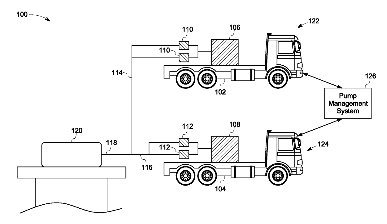
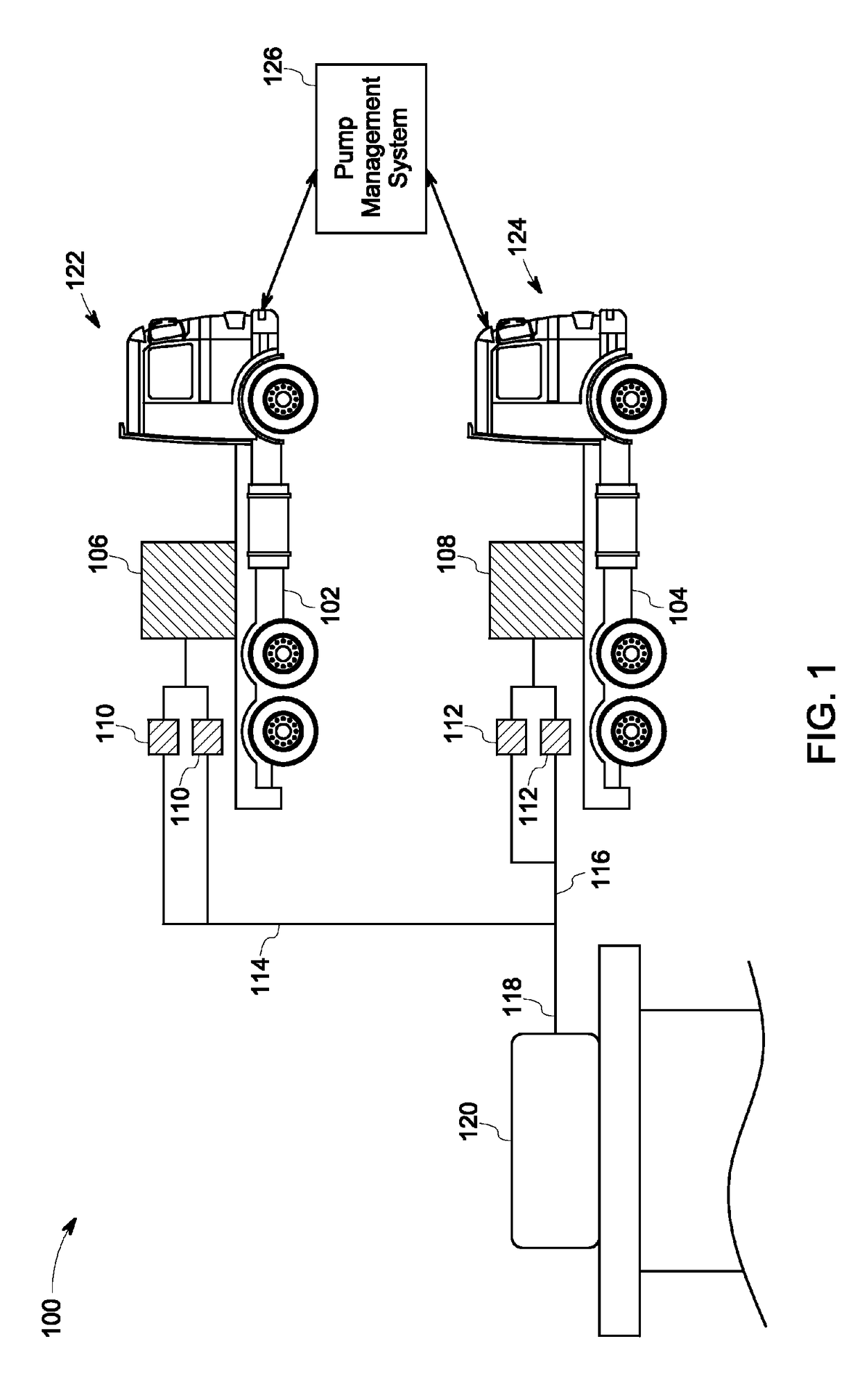
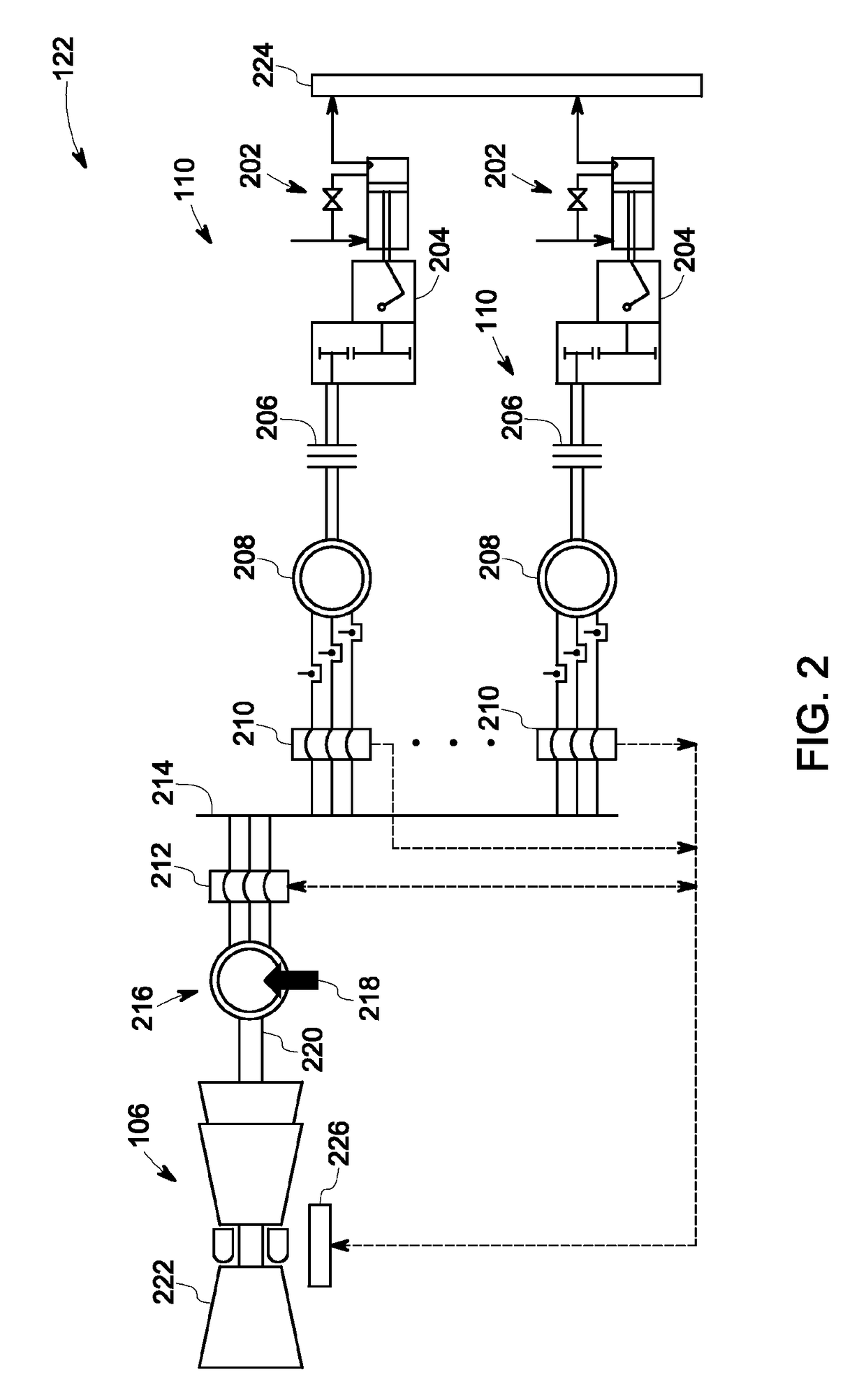
[0022]The embodiments described herein are directed to management of operation of a distributed pumping system. Specifically, the management of operation of the distributed pumping system includes power management of a plurality of generator-units, performance assessment and protection of a plurality of pump-units. The technique includes receiving a pump-unit parameter from the at least one pump and a generator-unit parameter from the at least one generator-unit. An operating set-point is determined based on the motor-unit parameter and the generator-unit parameter.

[0023]The term ‘dispatching’ used herein refers to scheduling the operation of a plurality of prime movers to produce the desired energy at the lowest fuel cost. The term ‘pressure profile’ referred herein means a desirable power output (or a pressure of working fluid) as a function of time for a specific purpose such as a fracking a formation at a site. The term ‘pump-unit’ refers to a conventional mechanical pump driven...


PUM


Abstract

A method implemented by at least one processor includes receiving a pressure profile to be generated by a pumping system, wherein the pumping system includes at least one pump-unit powered by at least one generator-unit. The method also includes receiving a pump-unit parameter from at least one pump-unit and a generator-unit parameter from at least one generator unit. The pump-unit parameter is representative of an operating parameter of the pump-unit. The generator-unit parameter is representative of an operating parameter of the at least one generator-unit. The method includes generating an operating set-point corresponding to the at least one generator-unit based on the pump-unit parameter and the generator-unit parameter, wherein the operating set-point is one of at least one operating set-point corresponding to the at least one generator-unit. The method also includes determining an input parameter for the at least one generator-unit based on the at least one operating set-point.

Description

BACKGROUND[0001]A system and method are disclosed for management of motor driven pumps. Specifically, the techniques are disclosed for efficient operation of a plurality of motor driven pumps powered by one or more prime movers.[0002]Hydraulic fracturing is used to generate production from un-conventional oil and gas wells. The technique includes pumping of fluid into a wellbore at high pressure. Inside the wellbore, the fluid is forced into the formation. Pressurized fluid entering into the formation creates fissures releasing the oil or gas. The fluid such as water or gas together with solid proppants is introduced into the fissures to sustain the release of oil or gas from the formation. The pumping is performed using boost and fracturing pumps which are powered by large diesel generators. More than one pump may be operating in an oil well and one or more diesel generator may be used to provide power to these multiple pumps.[0003]Electric motor driven pumps such as fracturing pum...

Claims


Application Information

Patent Timeline
Patent Type & Authority Patents(United States)
IPC IPC(8): E21B43/12F04B49/06F04B47/02F04B17/03F04D15/00
CPCF04D15/0066E21B43/12F04B17/03F04B47/02F04B49/065F04D15/0077F04B2203/0201
Inventor WIEGMAN, HERMAN LUCAS NORBERTARAVIND, DEEPAK
Owner HYDRIL USA DISTRIBUTION LLC
Learn More