
Portable curtain retraction device and system

a curtain and retraction device technology, applied in the field of portable retraction devices and systems, can solve the problems of cumbersome or time-consuming erecting, uneven presentation, etc., and achieve the effects of convenient replacement, convenient manufacture and configuration of components, and sufficient disassembly of components

Active Publication Date: 2017-03-21
TAIT TOWERS
View PDF38 Cites 0 Cited by
  • Summary
  • Abstract
  • Description
  • Claims
  • Application Information

AI Technical Summary

Benefits of technology

[0008]An advantage of an embodiment of the present invention is that the system of the present invention is portable and allows sufficient disassembly of the components to permit transport over land, sea or by air.
[0009]Another advantage of an embodiment of the present invention is that the detachable components, including the drum for drawing in and deploying the lines and the barrier, are easily and quickly replaceable in the event of malfunction or damage.
[0010]Still another advantage of an embodiment of the present invention is that the devices for drawing in and deploying the line are interchangeable and permit easier manufacture and configuration of components in systems having a plurality of barrier retraction devices.
[0011]Still another advantage of an embodiment of the present invention is that the device may be assembled onto frames of substantially any geometry and at substantially any or variable heights, providing for easy installation.
[0012]Still another advantage of an embodiment of the present invention is that assembly / disassembly of the portable retraction devices may be accomplished quickly and easily requiring little or no technical skill.
[0013]Still another advantage of an embodiment of the present invention is that individual retraction devices are independently controllable to permit individual sizing of the lines, allowing for quicker installation and reduced error in setup.

Problems solved by technology

These known systems suffer from the drawback that they are not sufficiently portable, they do not provide flexibility in measuring the lengths of the strings drawing the curtain, resulting in an uneven presentation, and / or they are cumbersome or time-consuming to erect.

Method used


Image

  • Portable curtain retraction device and system
  • Portable curtain retraction device and system
  • Portable curtain retraction device and system

Examples


Embodiment Construction

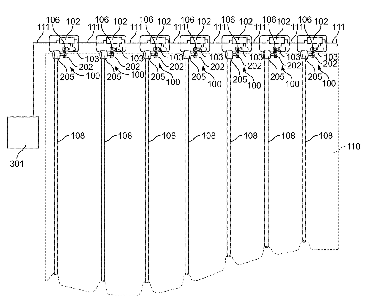
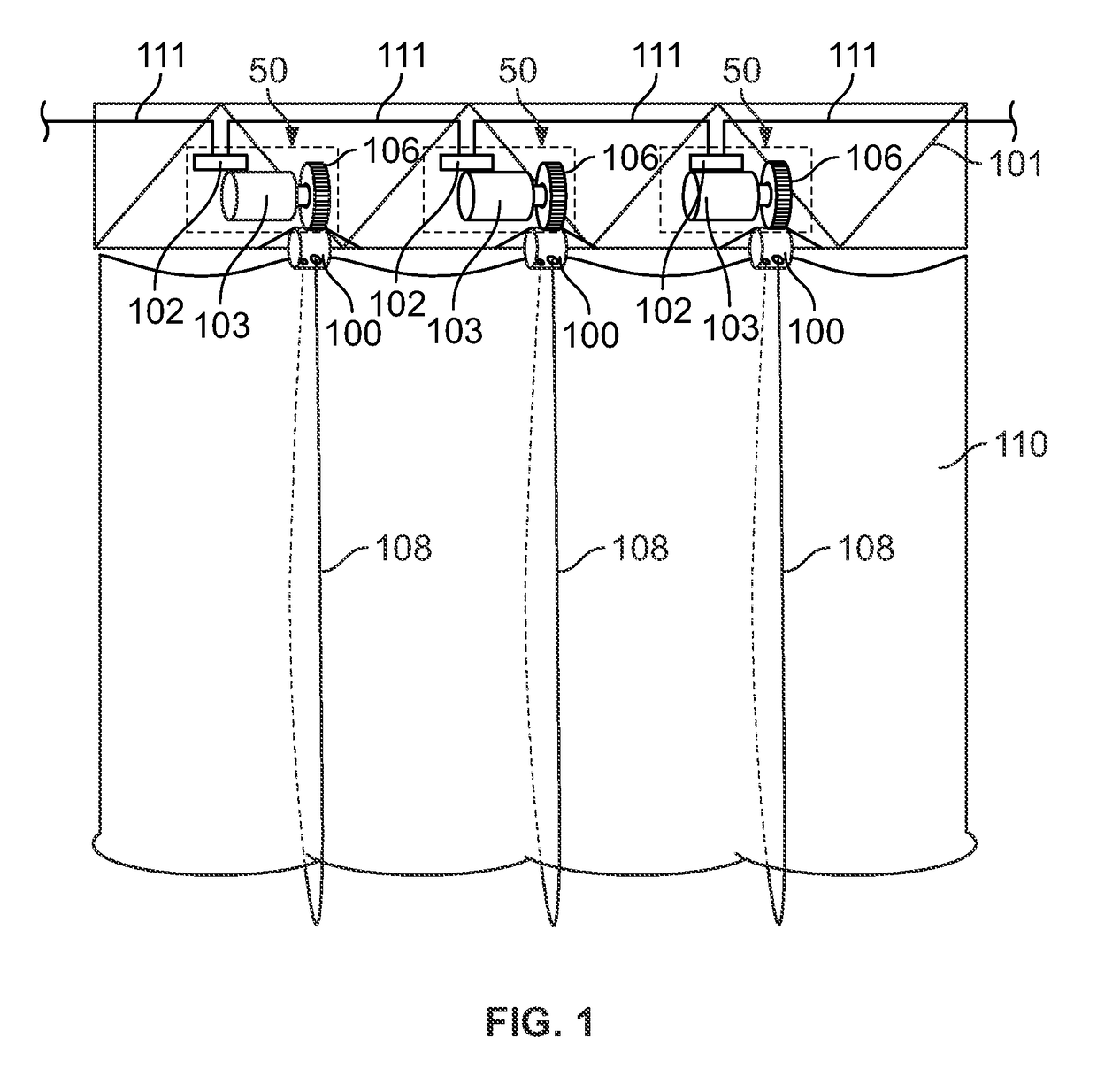
[0022]FIG. 1 shows a portable barrier retraction system that includes a portable barrier retraction device 50 mounted to a support frame 101 having deployed soft-goods or barrier 110, shown as an Austrian-type curtain. Barrier 110 is preferably soft-goods, such as a curtain, fabric, sheet, tarp or screen, or other retractable barrier material that provides the desired visual effect. For example, barrier 110 may form a scalloped or festooned appearance along one or more edges of the barrier 110 while being retracted and preferably maintains the festooned appearance in the retracted barrier 110. The festooning may be provided by drawing lines 108 into a detachable drum 100 resulting in a shorted line 108 around or attached to barrier 110, thereby drawing the barrier 110 upward with respect to the direction of gravity. Likewise, a retracted barrier 110 may be deployed, wherein line 108 is lengthened and barrier 110 is allowed to extend downward, preferably assisted by force of gravity....


PUM


Abstract

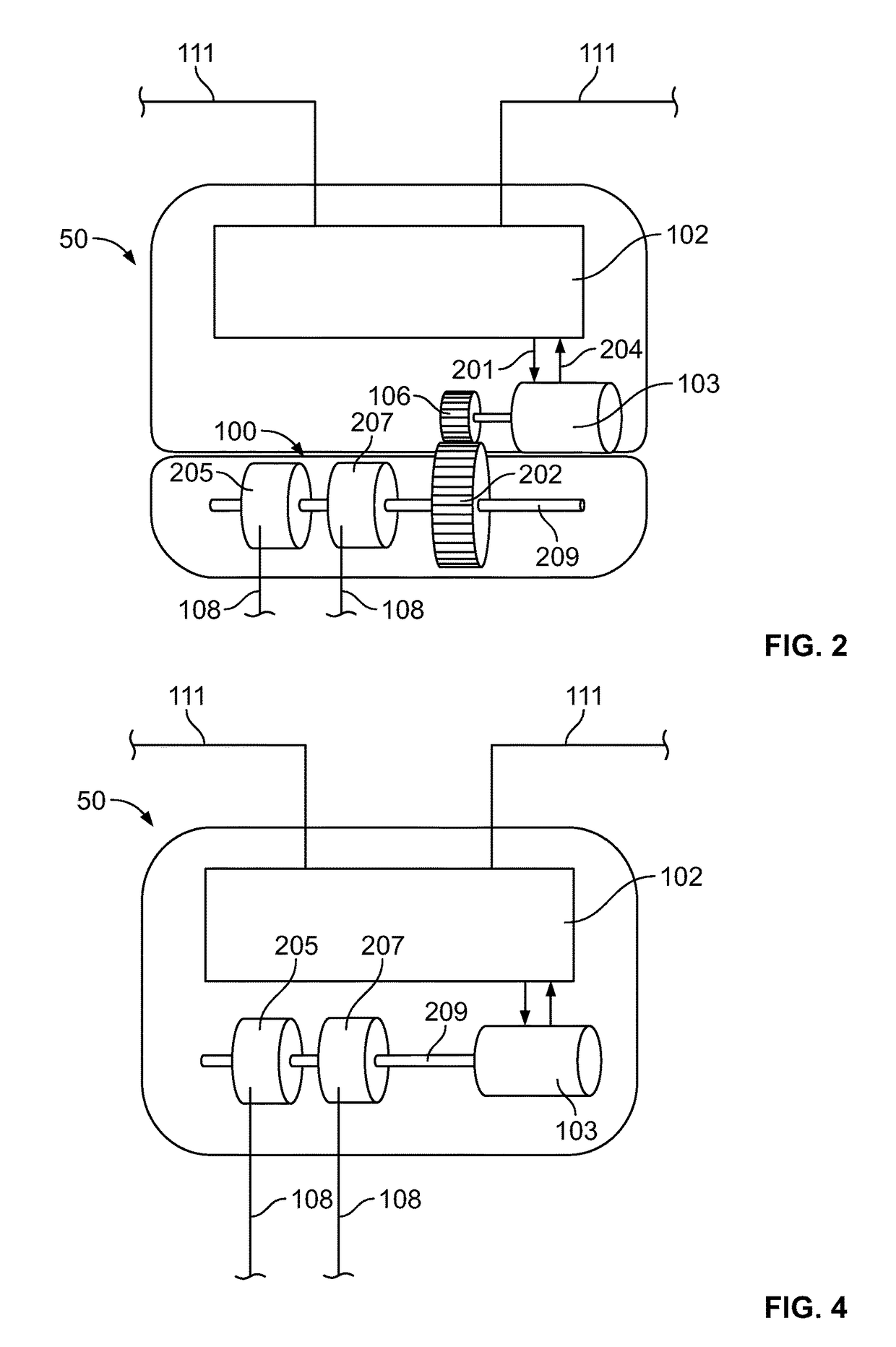
A portable barrier retraction device having a drive motor with an addressable drive motor control. The drive motor control is capable of being connected in a serial arrangement with one or more other addressable drive motor controls. The drive motor is in rotational communication with at least one retraction assembly configured to retract or deploy a line in response to rotation of the drive motor. The line is configured to retract or deploy a barrier. The drive motor provides selective rotation in response to an addressed signal from a controller. In addition, retraction systems employing portable retraction devices and methods for assembling the retraction systems are also disclosed.

Description

FIELD OF THE INVENTION[0001]The present invention is directed to portable retraction devices. In particular, the present invention is directed to a portable retraction device and system for theatrical barriers.BACKGROUND OF THE INVENTION[0002]In the production of many theatrical events, including concerts and public events, barriers or curtains are utilized to provide particular visual effects. For example, an opaque curtain may be utilized prior to the performance to conceal areas from view, while providing a decorative surface for viewing by the audience. Other visual effects may also be provided wherein, for example, transparent or semi-transparent material may be utilized to create various visual effects by front-lighting, back-lighting or by projecting images thereon. These barriers are typically retractable, partially or fully out of view by the audience and / or may be retracted or drawn in a decorative festoon pattern, such as in an Austrian-type or French-type curtain.[0003]T...

Claims


Application Information

Patent Timeline
Patent Type & Authority Patents(United States)
IPC IPC(8): E06B9/36A47H5/032
CPCE06B9/36A47H5/0325
Inventor DAVIS, ADAMFAIRORTH, JAMESTAIT, MICHAEL
Owner TAIT TOWERS
Learn More