
Light receiving module having built-in wavelength-tunable wavelength-selective filter

a light receiving module and wavelength selectivity technology, applied in the direction of optics, instruments, optical light guides, etc., can solve the problems of low wavelength selectivity, difficult to know whether the laser light becomes parallel, and difficult to convert light having the features of emissive light outside the light receiving element into parallel light inside the light receiving element, etc., to achieve the effect of wavelength selectivity

Active Publication Date: 2017-01-17
PHOVEL
View PDF17 Cites 2 Cited by
  • Summary
  • Abstract
  • Description
  • Claims
  • Application Information

AI Technical Summary

Benefits of technology

The present invention solves a problem in optical coupling where a wavelength-selective filter cannot effectively filter out light due to its incident angle. The invention makes the laser light coming into the light receiving element parallel to the filter, allowing it to select more wavelengths. This results in an improved coupling of optical fibers to light receiving elements.

Problems solved by technology

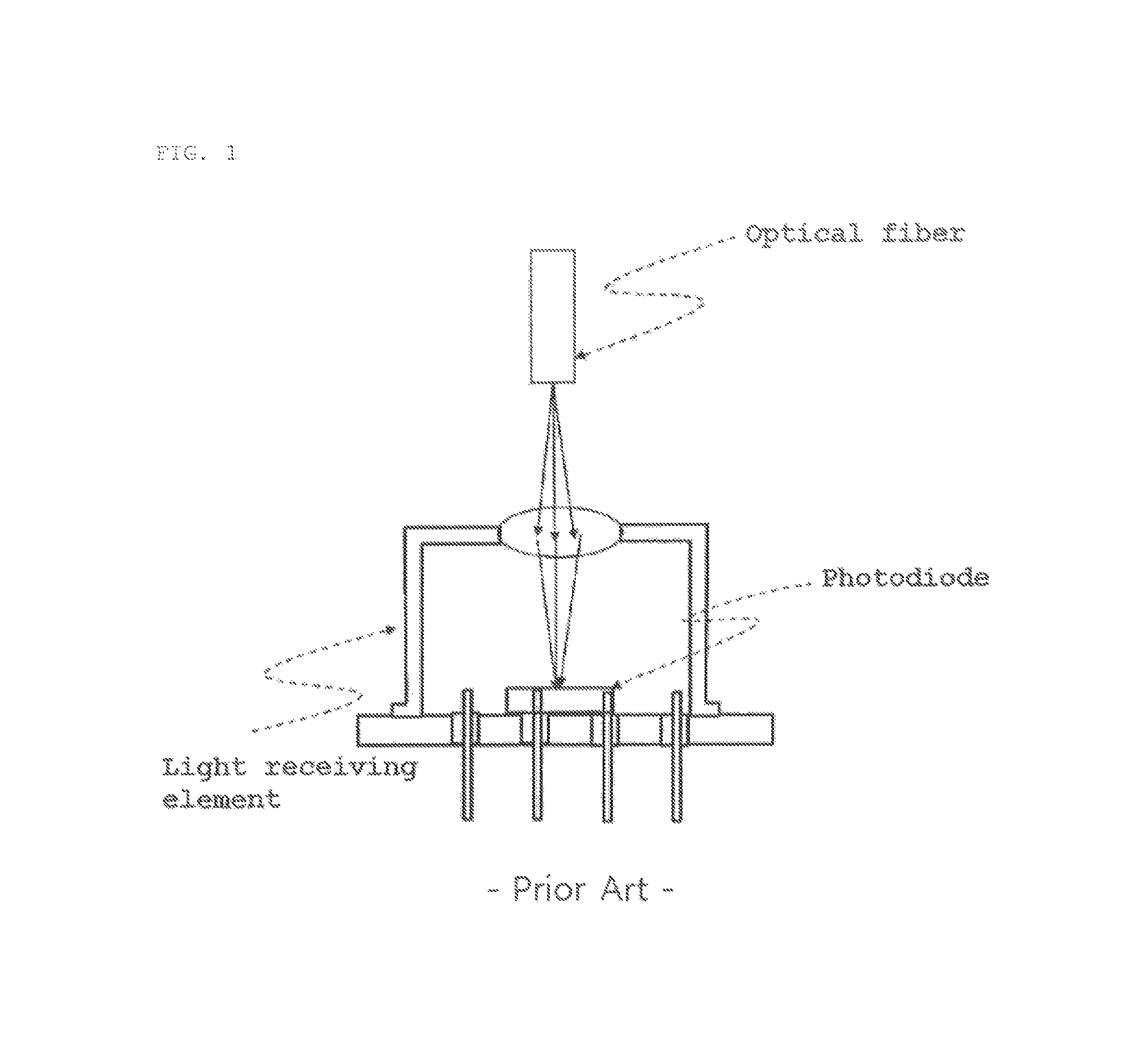
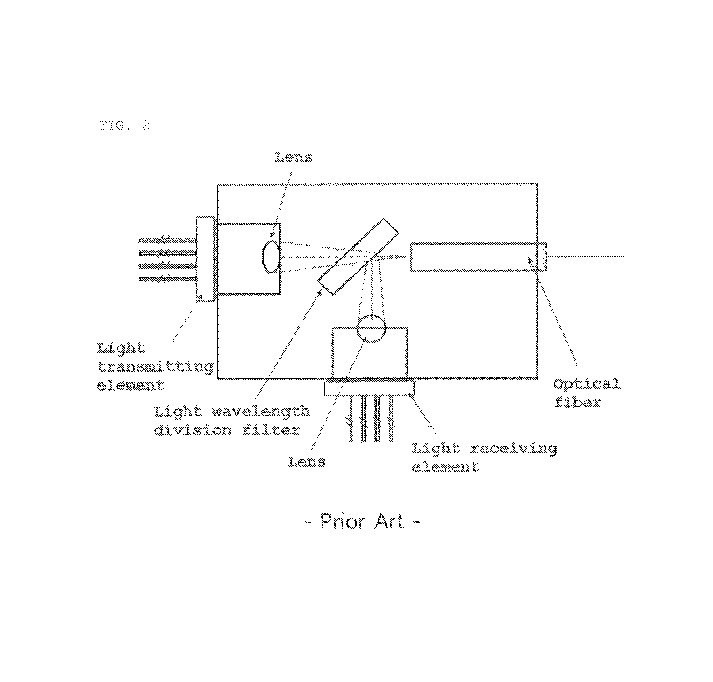
However, when optical arrangement is achieved, as described above, the features of parallel light, converging light, and emissive light that laser light has in the light receiving element 22 depend on the degree of the optical arrangement, and a change in convergence of light is a phenomenon generated in the light receiving element 22, so it is difficult to know whether the laser light becomes parallel light in the light receiving element 22 in optical arrangement.
Accordingly, it is very difficult to convert light having the features of emissive light outside a light receiving element into parallel light inside the light receiving element, using a lens attached to the light receiving element in the light receiving module illustrated in FIG. 1 and the optical module for bidirectional communication illustrated in FIG. 2.
Therefore, when the light receiving element is a wavelength-tunable light receiving element, it is difficult to make the laser light traveling into a wavelength-tunable selective filter into parallel light, so wavelength selectivity is low.

Method used


Image

  • Light receiving module having built-in wavelength-tunable wavelength-selective filter
  • Light receiving module having built-in wavelength-tunable wavelength-selective filter
  • Light receiving module having built-in wavelength-tunable wavelength-selective filter

Examples


Embodiment Construction

[0019]Hereinafter, preferred embodiments of the present invention are described in detail with reference to the accompanying drawings.

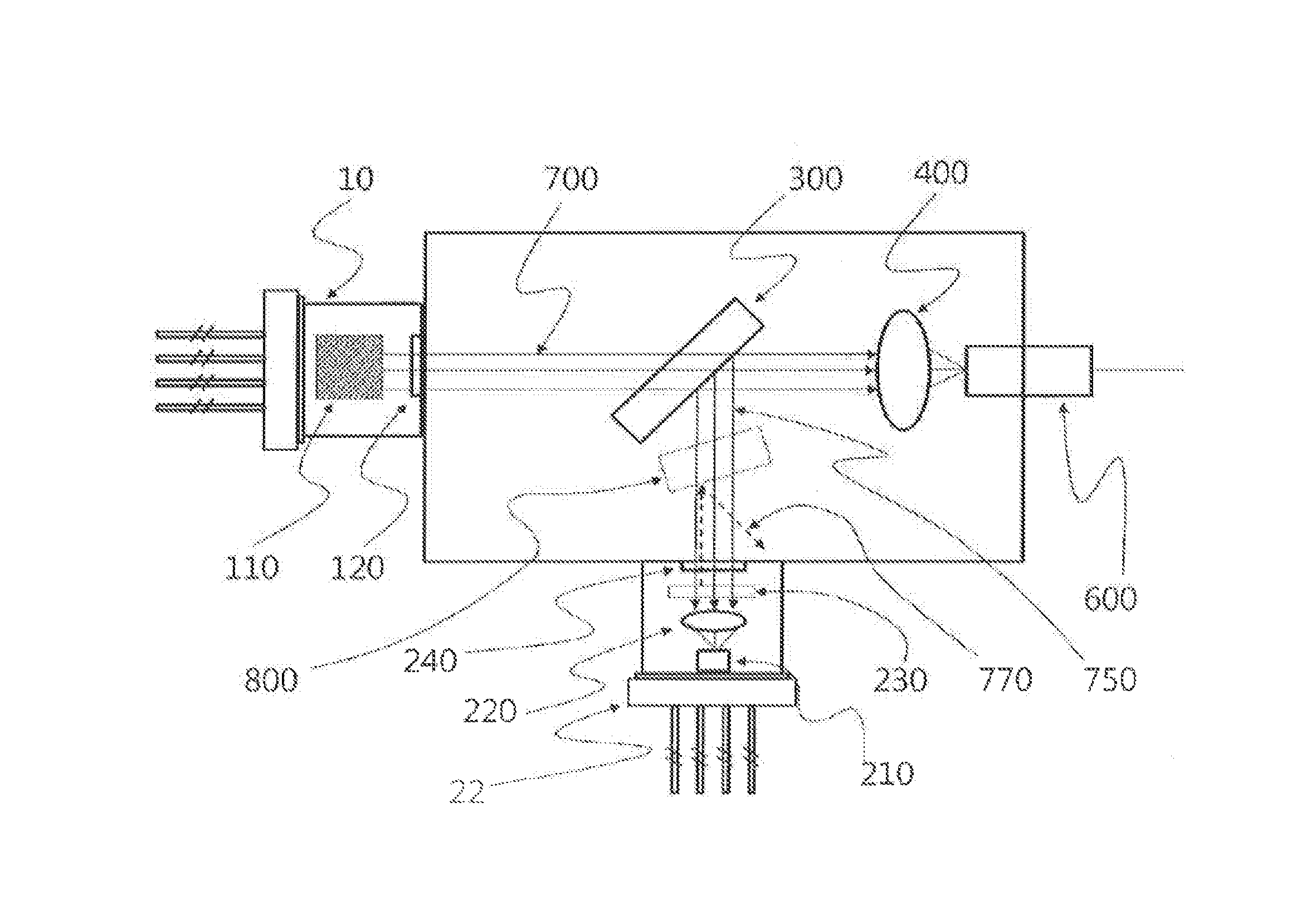
[0020]FIG. 6 is a diagram illustrating the configuration of a light receiving element having a built-in wavelength-tunable wavelength-selective filter using parallel light according to an embodiment of the present invention.

[0021]As illustrated in FIG. 6, an optical signal is outputted as emissive light having a predetermined emission angle from an optical fiber 600. The optical signal from the optical fiber 600 is converted into parallel light through a lens 400 separated from a light receiving element 22. The optical signal converted into parallel light by the lens 400 separated from the light receiving element 22 travels into the light receiving element 22 through a flat plate-shaped window 240. A wavelength-tunable wavelength-selective filter 230 having a flat plate shape is disposed in the light receiving element 22 and only the light having wave...


PUM


Abstract

A light receiving module having a built-in wavelength-tunable wavelength-selective filter that can selectively receive light with a specific wavelength from laser light with various wavelengths emitted from an optical fiber and tune the specific wavelength. In the light receiving module including a light receiving element having a built-in wavelength-tunable wavelength-selective filter that receives laser light from an optical fiber according to the present invention, a flat plate-shaped window (240) transmitting laser light from an optical fiber (600) is formed in the light receiving element (22), a wavelength-tunable wavelength-selective filter for separating wavelengths of laser light traveling as parallel light is disposed in the light receiving element (22), and a lens (400) converting laser light from the optical fiber (600) into parallel light is disposed between the optical fiber (600) and the light receiving element (22).

Description

TECHNICAL FIELD[0001]The present invention relates to a light receiving module having a built-in wavelength-selective filter, and more particularly, to a light receiving module having a built-in wavelength-tunable wavelength-selective filter that can selectively receive light with a specific wavelength from laser light with various wavelengths emitted from an optical fiber and can tune the specific wavelength. Further, the present invention relates to a light receiving module for bidirectional communication that includes a wavelength-tunable receiver that can tune and selectively receive a light receiving wavelength from an optical fiber. The light receiving module optically couples a light transmitting element that outputs parallel light and an optical fiber, using one lens attached to the optical fiber and making laser light used for transmitting / receiving optical signals into parallel light, and optically couples a light receiving element that receives parallel light and an optic...

Claims


Application Information

Patent Timeline
Patent Type & Authority Patents(United States)
IPC IPC(8): G02B6/42G02B27/14G02B6/293G02B6/32
CPCG02B27/141G02B6/4215G02B6/29395G02B6/325G02B6/4209G02B6/4246G02B6/29361G02B6/4206G02B6/4208G02B6/42
Inventor KIM, JEONG-SOO
Owner PHOVEL
Learn More