One of the limitations of the conventional injection molding processes is that large diameter handles cannot be produced in an efficient manner, due to the cost of increased material and lengthened cooling times, resulting from the increased mass of material used.
Due to their low strength, however, toothbrushes made entirely from high-friction, low-durometer material are unlikely to exhibit the bend strength necessary to provide adequate force to brush in a conventional grip style.
First—the toothbrush is more expensive due to the use of more plastic to make the toothbrush. The material used to create the toothbrush handle increases approximately with the square of the diameter of the handle.
Second—the cost of manufacture is increased because the time needed to cool and solidify the toothbrush increases considerably. The increased cooling time is due both to the increased quantity of hot plastic, and the larger cross section of the toothbrush. As plastic has a relatively low thermal conductivity, extracting heat from the center of the brush is substantially more difficult with an increased cross section. It is known to those familiar in the art that overall cooling time for all molding cycles for a multi-component brush can be minimized by balancing the size of each shot of plastic so that the brush is substantially uniformly divided by weight for each component, however this has the drawback of requiring a greater fraction of use of an expensive material, typically TPE, than would otherwise be required. In essence, both material use and capital equipment time cannot both be simultaneously optimized for this type of injection molded toothbrush.
Third—most thermoplastics shrink during cooling and solidification. Shrinkage can be mitigated by packing additional molten plastic into the center of the handle through the injection gate as the outer edges of the handle cool, however this mitigation loses effectiveness as the injection gate is placed away from the thickest portion of the handle and placement of the gate, which will have some tactile vestige, in the thick, gripping portion of the handle can lead to dissatisfaction during use. For many toothbrush handle designs, packing alone cannot mitigate the visible surface shrinkage and surface defects and internal defects associated with an increased handle cross section. These surface defects can be manifested as unintentional variations in surface gloss or texture, which contribute negatively to the look and feel of the part. Internal defects can be manifested as voids or bubbles inside the plastic, which can weaken the handle visibly or invisibly, depending on the degree of transparency of the plastic. It is known to those familiar in the art that a second component can be used to cover or hide negative cosmetic features such as gate vestiges or sink marks, however this cannot by nature work on the final shot which must necessarily have an uncovered gate vestige and may also contain sink marks in thick sections.
Fourth—the filling and packing of a thick-wall plastic parts in the injection mold cavity requires very high pressures, typically thousands of pounds per square inch, which necessitates mold cavities made from very high-strength materials, which are expensive and time-consuming to create. These extremely high pressures can in fact limit the speed of the manufacturing process by requiring complete or near-complete cooling and / or solidification of one plastic shot prior to injection of a subsequent shot.
Fifth—the injection of multiple shots of plastic in multiple steps necessarily requires each component of material to have at least one unique mold cavity portion which significantly adds to expense, complexity and difficulty in molding, especially where plastic and metal meet to form an edge, also known as a shutoff.
Sixth in multi-cavity production, the balance of fill between shots is especially difficult to control with TPEs, as they have a narrow range of processing temperatures and their viscosities do not vary substantially over this range.
Such injection molding processes using additional air injection have substantial difficulty forming hollow handle bodies with substantially uniform wall thickness, and as such, the potential for optimization of a handle for maximum ergonomic function in minimum material weight and manufacturing efficiency is limited.
A further drawback to such injection molding processes in U.S. Pat. No. 6,818,174 B2 is the creation of a vent hole for the gas.
The vent hole is formed at the interface of molten plastic and high-pressure gas (and not by mold steel) and thus cannot be made predictably or with high precision.
A still further drawback of hollow-handled toothbrushes made using gas-assist injection molding relates to the application or installation of a second, third or subsequent material to the toothbrush by injection molding, or overmolding, where the overmolded material may, in the process of sealing the necessary gas vent, intrude substantially into the hollow void created in the first gas injection step, as there is nothing to stop it besides friction and the near-atmospheric pressure inside the void.
While this may still result in a cosmetically-acceptable part, it prevents use of shot-size-limiting devices such as valve gates and can add substantially to the cost of the part.
Gas-assist injection molding does not substantially reduce injection pressure or melt energy required to form a plastic article.
This manufacturing method still has the drawbacks of: requiring the complete melting of plastic at every molding step, high pressures at every molding step, associated equipment involved with injection molding at every molding step, and in addition may have added labor expense associated with both in-mold and out-of-mold assembly of discretely-molded parts, plus the added expense and inconvenience of multiple steel cavity sets per part manufactured.
The use of injection molding to create multiple discrete parts has also the disadvantage that each part must not contain any substantial undercut from which the mold core forming a concave surface of the injection-molded part could not be extracted from the part after molding; or in the case where such undercut exists, it must be created carefully by means such as collapsing mold cores and is thus subject to extensive constraints on the surrounding geometry.
Further, mold cores must typically contain some mechanism to cool or remove heat, and would thus be difficult or impossible to create to make internal geometry for most manual toothbrushes which may have diameters of 10 mm and lengths beyond 150 mm.
These methods all have disadvantages however in long-term adhesion, especially to thermoplastics with less-active surfaces made from materials such as polypropylenes.
Electromechanical toothbrushes in particular are susceptible to problems of assembly, as they are necessarily hollow in order to include batteries, motors and associated electrical linkages and drive components which must be all placed inside with some degree of precision.
Such a large opening would be a drawback in a non-electromechanical handle, which has no need to accommodate internal component entry, and would necessitate an overly-large second part or cap to prevent intrusion and collection of water, paste, saliva and other detritus of conventional use.
Such an overly-large opening, if positioned near the head, would interfere substantially with ergonomic use of the brush.
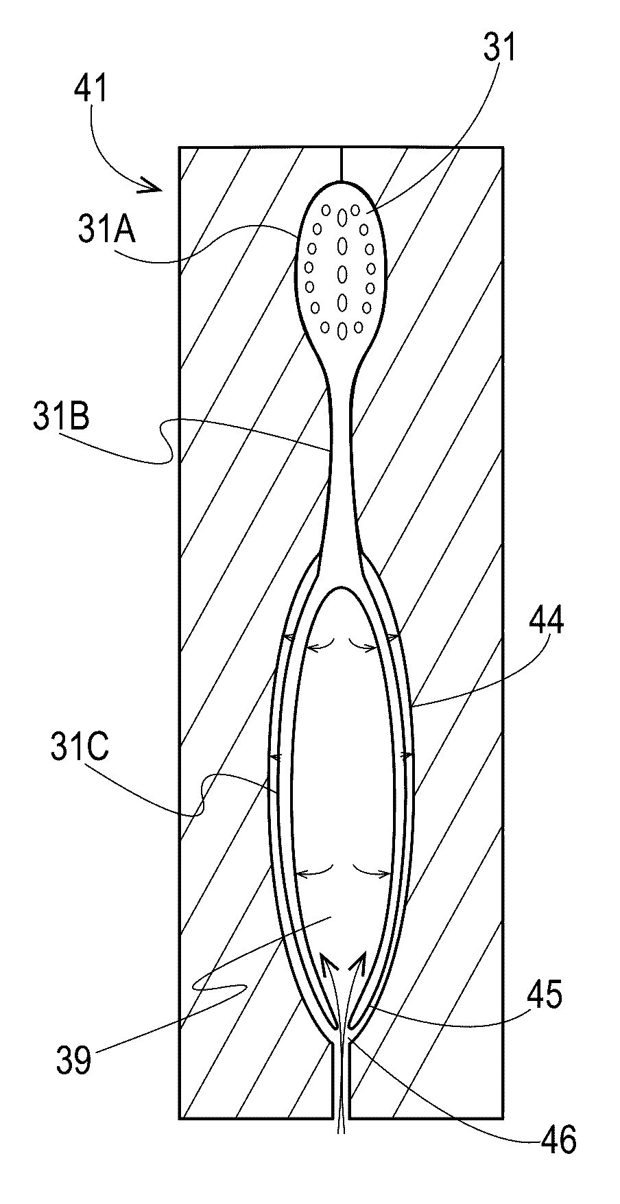
Additional constraints to the geometry on the inside surface of the cavity, for example to locate motors, housings, batteries, etc. which must be positioned inside accurately as to be rigidly fixed will also be detrimental to the overall blow molding process, as the majority of the inner cavity surface of a blow molded part cannot be defined directly by steel in the mold surfaces, and is instead defined indirectly by steel on the outer surface of the handle combined with the wall thickness of the parison, blowing pressure and stretch ratio of the final part to the original parison or preform thickness.
Such constraints of these process variables will necessarily limit manufacturing efficiencies.
An internal frame or cap, as described in WO 2004 / 077996 can be used to provide this necessary strengthening mechanism in an electromechanical toothbrush, but would be a drawback to a manual brush, which must contain no additional components to function adequately, in extra expense, complexity and additional load-bearing parts.
Such a second opening would be unnecessary for a manual toothbrush and would create drawbacks in the need for additional seals and mechanical fasteners.
To reduce weight while maintaining stiffness, some toothbrush handles are made from bamboo or balsa wood, however these materials have disadvantages in that they are not easily formable into complex three-dimensional shapes which can be comfortably gripped.
Both carbon fiber and glass-filled thermoplastic composites also tend to fail in a brittle manner, with little ductility.
This type of failure is undesirable in a device that is placed in the mouth: More desirable is a device which, when subjected to loads substantially greater than their design loads, fail first in some permanent bending mode versus a sudden fracture.
Further, these materials do not contain intrinsically all of the properties necessary to create light weight, strength in bending and soft-touch, high-friction grip.
This alignment of the grain also can present a specific disadvantage to woods in general in that the presentation of splinters of material is most likely to occur in the direction aligned to typical forces applied by the hand during brushing.
The overall weight savings possible with foamed plastics may be limited however, as the bubbles inside the plastic which create the weight savings also create stress concentrations which will severely reduce strength in tension and can reduce ductility.
While foamed plastics can provide substantial strength in compression (and are used for exactly this purpose in applications such as packing materials where material weight combined with resistance to compressive crushing is a critical issue) the weakness in tension severely affects bending strength and prevents uniformly-foamed plastics from serving as load-bearing elements in articles which must maintain strength and stiffness in bending during normal use.
While these articles can be both stiff and strong in bending, they also generally contain drawbacks which would limit their general use in semi-durable, Class-I medical devices, such as toothbrushes.
First, such articles typically contain significant flash along parting lines, or in any locations where the parison is larger in cross sectional area than is the cavity to which it is blown.
Second, most articles contain some significant vestige of blowing in the form of a hole, which may be accurately or inaccurately formed.
Such a vestige would be regarded as a significant defect in a Class-I medical device which must prohibit breach or entry of contaminants to a hollow interior which does not drain effectively.
Such articles exist in the form of small, typically squeezable, tubes or bottles which in fact benefit from having a very thin, deformable wall which enables dispensing of internal contents, making them unusable or significantly inferior as toothbrushes.
Extrusion and injection-blow-molded handles for single-component semi-durable consumer goods such as feather dusters and tape dispensers are also known, but again these articles would not meet criteria for semi-durable Class I medical devices, specifically with regard to the sealing of the necessary blowing orifice against intrusion of water or other contamination, and in the case of extrusion blow molding, in the appearance of flash on the articles in areas that would directly contact or go into the mouth.
These articles can also be brittle, and when too much force is applied, can break or snap suddenly and without ductility, producing sharp edges, making them unusable for use in the oral cavity.
While these articles do provide the advantage of a large gripping surface which is improved by addition of a high-friction textured surface, they are by nature highly-deformable or squeezable packages designed for liquid storage and dispensing and would serve poorly as toothbrushes as there is no obvious method to attach bristle tufts without injection molding.
It has also been proposed to manufacture hollow toothbrushes, however no existing disclosure in the prior art addresses the issues of: Strength in bending, stiffness in bending, overall rigidity, mitigation of flash or other sharp defects, variations in cross-sectional area, and obstruction or sealing of the blow hole vestige.
