
Transparent microdisplay in head mountable displays

a technology of transparent micro-displays and display cases, applied in optics, instruments, static indicating devices, etc., can solve the problem of limited use of niche markets

Active Publication Date: 2016-08-30
GOOGLE LLC
View PDF5 Cites 22 Cited by
  • Summary
  • Abstract
  • Description
  • Claims
  • Application Information

AI Technical Summary

Benefits of technology

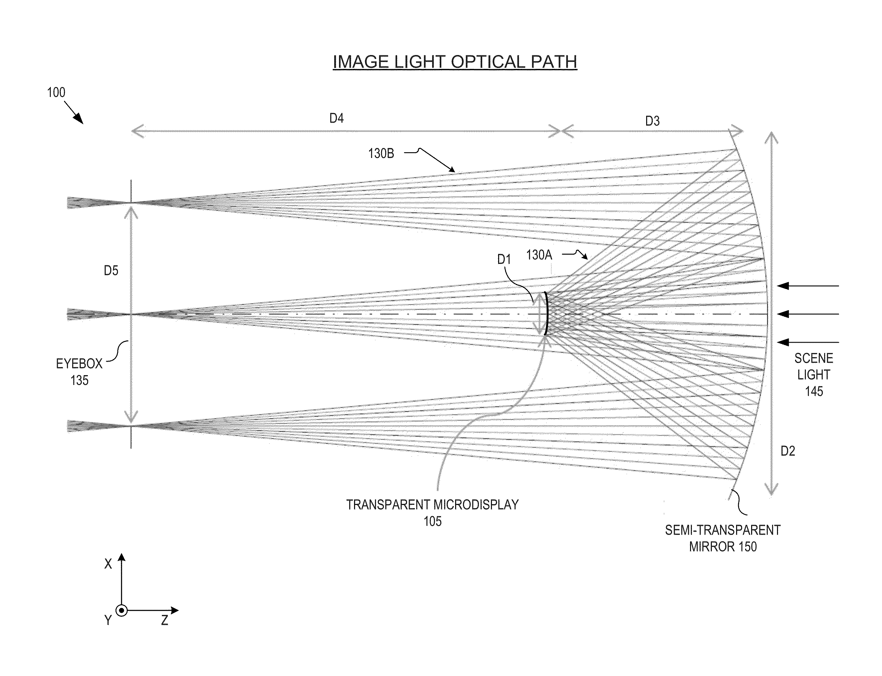
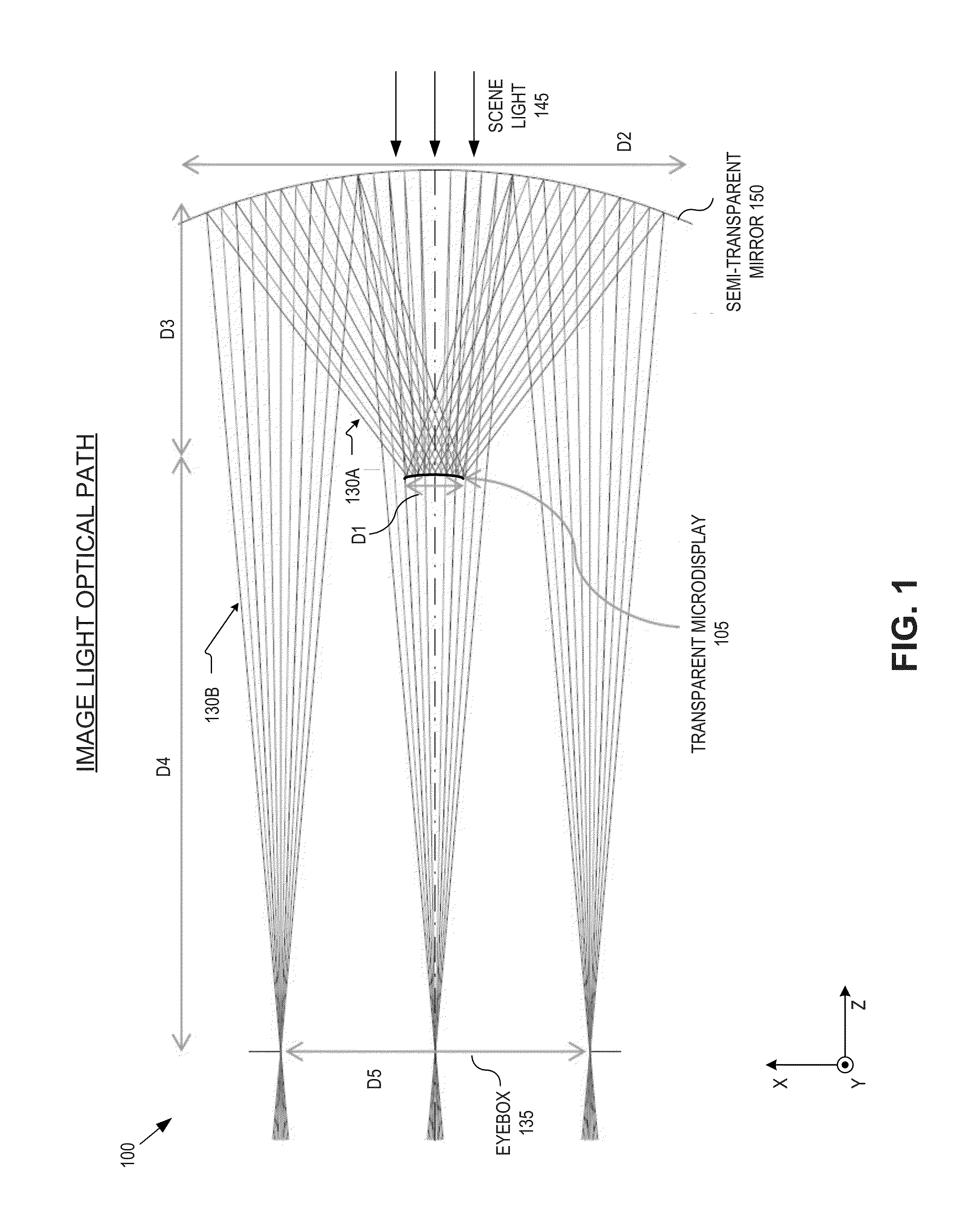
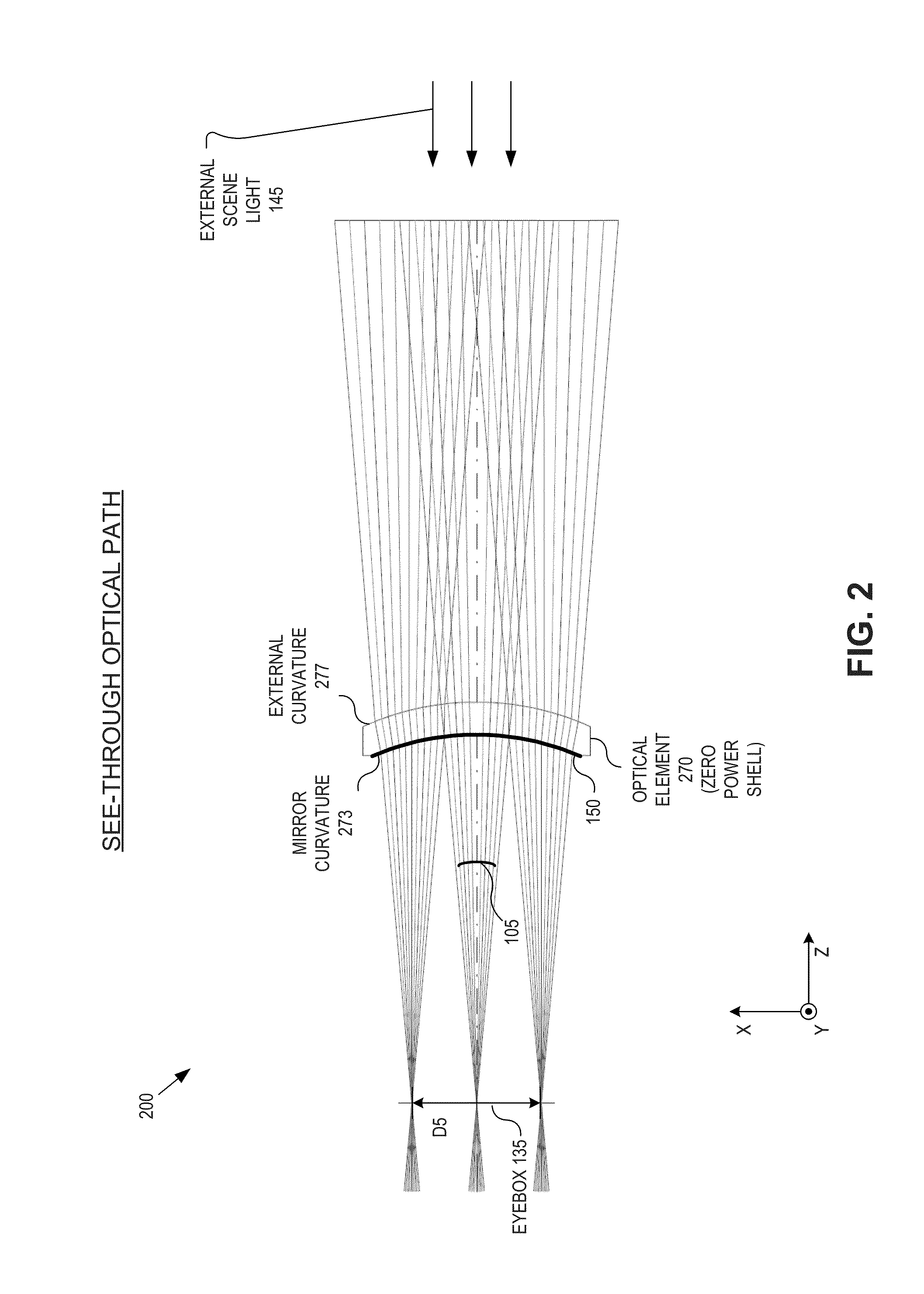
The patent text describes a new optical system for head mountable displays (HMDs) that uses a transparent microdisplay and a curved mirror to combine image light from two different fields. This system aims to provide a low-cost, compact, lightweight, durable, and good quality image without undue optical aberration. The technical effect of this invention is to enable a more widespread adoption of HMDs outside of niche markets by providing a low-cost, optical combiner that is compact, lightweight, durable, and provides a good quality image without undue optical aberration.

Problems solved by technology

The above mentioned optical combiners each have their own respective drawbacks, which have limited their use to niche markets.

Method used


Image

  • Transparent microdisplay in head mountable displays
  • Transparent microdisplay in head mountable displays
  • Transparent microdisplay in head mountable displays

Examples


Embodiment Construction

[0012]Embodiments of an apparatus and a system for utilizing a transparent microdisplay in a head mountable display (“HMD”) are described herein. In the following description, numerous specific details are set forth to provide a thorough understanding of the embodiments. One skilled in the relevant art will recognize, however, that the techniques described herein can be practiced without one or more of the specific details, or with other methods, components, materials, etc. In other instances, well-known structures, materials, or operations are not shown or described in detail to avoid obscuring certain aspects.

[0013]Reference throughout this specification to “one embodiment” or “an embodiment” means that a particular feature, structure, or characteristic described in connection with the embodiment is included in at least one embodiment of the present invention. Thus, the appearances of the phrases “in one embodiment” or “in an embodiment” in various places throughout this specifica...


PUM


Abstract

An optical apparatus includes a transparent microdisplay and a curved mirror. The transparent microdisplay has an array of self-illuminating emitters configured to emit image light propagating in an external direction. The curved mirror is positioned to reflect the image light toward an eye-ward side of the optical apparatus. A first curvature of the curved mirror has an optical power configured to focus the image light reflected by the curved mirror within an eyebox sized area. The transparent microdisplay is disposed between the curved mirror and the eyebox sized area.

Description

TECHNICAL FIELD[0001]This disclosure relates generally to the field of optics, and in particular but not exclusively, relates to transparent microdisplays in Head Mountable Displays (“HMDs”).BACKGROUND INFORMATION[0002]In the field of optics, a combiner is an optical apparatus that combines two images together, from either the same side of the combiner (reflective / reflective, or transmissive / transmissive) or from the two different sides of the combiner (reflective / transmissive). Often times, optical combiners are used in heads up displays (“HUDs”), sometimes referred to as head mountable displays (“HMDs”) or near-to-eye displays, which allow a user to view a display image superimposed over an external view. The HUD enables the user to view the display image without having to look away from her usual viewpoint. The term HUD originated from its use in avionics, which enabled a pilot to view information while looking forward with his head up, as opposed to looking down at an instrument...

Claims


Application Information

Patent Timeline
IPC IPC(8): G02B27/14G02B27/01G09G5/00
CPCG02B27/0172G02B17/06G02B2027/0147G02B2027/0196
Inventor CAKMAKCI, OZANGUPTA, ANURAG
Owner GOOGLE LLC
Learn More