
Contactless switch with shielded vane

Active Publication Date: 2016-08-23
EATON INTELLIGENT POWER LIMITED
View PDF22 Cites 7 Cited by
  • Summary
  • Abstract
  • Description
  • Claims
  • Application Information

AI Technical Summary

Benefits of technology

The patent describes different switch designs that use magnets and magnetic sensors to create a functioning switch. The switch includes a housing, a button or operating member, and magnet sensors and a magnet holder. The magnet holder is movable to position the magnets responsive to the button. A vane interrupter is used to protect the magnets and sensors from external magnetic fields. The switch designs can be used for various applications such as rocker switches or switches in industrial settings where protection from magnetic interference is necessary. Overall, the patent provides technical solutions for creating reliable and effective switches using magnets and magnetic sensors.

Problems solved by technology

With respect to contactless control switches that are utilized for one of various applications, it is recognized that existing designs of such switches can limit the performance thereof.
For example, existing contactless control switches constructions may suffer from issues regarding the ability of the magnetic sensors to detect the magnetic field with sufficient strength, such that discerning a distinct switching position may be difficult.
This problem of correctly discerning a distinct switching position may be further compounded if the switch is not constructed in a fashion that provides the magnetic sensors with sufficient protection from external magnetic fields, as the presence of such external magnetic fields interferes with the ability of the magnetic sensors to attribute a sensed magnetic field to the switch magnets.
While such shielding housings may be effective in providing magnetic shielding, it is recognized that the housing can be bulky and increase the size of the switch.
Such shielding housings can also increase the overall cost of the switch, as they necessitate the addition of an entirely separate / additional component to the switch.

Method used


Image

  • Contactless switch with shielded vane
  • Contactless switch with shielded vane
  • Contactless switch with shielded vane

Examples


Embodiment Construction

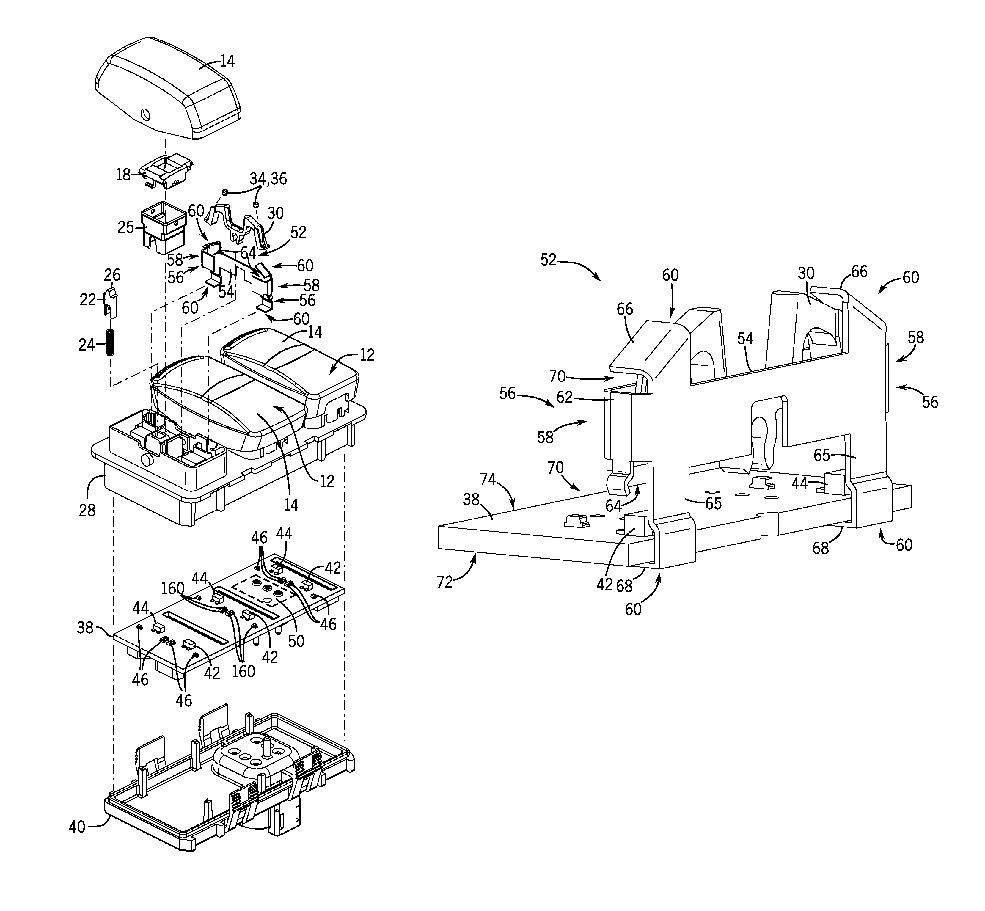
[0020]Embodiments of the present invention provide a contactless control switch that is resistant to the influence from external magnetic fields. The contactless control switch is constructed to have one or more moveable magnets that provide two or three distinct switching positions, with the magnets generating a magnetic field sensed by one or more magnetic sensors in the switch such that a distinct switching position of the control switch may be easily discerned. A shielded vane interrupter incorporated in the switch provides shielding to the one or more magnetic sensors from external magnetic fields, so as to improve the functionality of the contactless control switch and provide for better discernment of the distinct switching positions for the switch.

[0021]While contactless control switches are described here below as being employed as vehicle control switches, it is recognized that the switches could be used in applications outside of vehicle control switches. Accordingly, emb...


PUM


Abstract

A switch includes a switch housing, a button, a circuit board having at least one magnet sensor, and a magnet holder, including at least one magnet, movably mounted to the housing to move responsive to an actuation of the button. A vane interrupter in the switch includes a passage structure positioned proximate to each magnet sensor such that a respective magnet is movable at least partially within a passage defined by the passage structure, and a flange structure having a first flange and a second flange positioned on opposing ends of the passage structure, with the first flange positioned adjacent a portion of the magnet holder holding the magnet and with the second flange positioned adjacent a surface of the circuit board opposite a surface on which the at least one magnet sensor is positioned, such that the circuit board is positioned between the magnet holder and the second flange.

Description

BACKGROUND OF THE INVENTION[0001]The present invention relates generally to control switches and, more particularly, to a contactless control switch that includes a shielded vane therein to provide magnetic shielding to a magnetic sensor of the switch.[0002]Electrical switches are used as control switches for a variety of applications in various industries, with one such example being in specialty vehicle markets—such as heavy trucks, agricultural equipment, and construction equipment, for example—where the switches are employed to control the motor vehicle lighting, the windshield wipers, the rear windshield heating, the cruise control functions, the internal central locking and other functions on and off. Often the control switches are in the form of rocker switches that may be pushed by an operator to rotate / tilt from a neutral position (i.e., switched-off state) to one or more activated positions (i.e., a switched-on state) that control operation of an associated system / componen...

Claims


Application Information

Patent Timeline
IPC IPC(8): H01H36/02H01H23/12H01H13/14
CPCH01H36/02H01H23/12H01H13/14H01H23/145H01H36/00H03K17/97
Inventor LEE, DAVIN ROBERT
Owner EATON INTELLIGENT POWER LIMITED
Learn More