
Method for calibrating a measuring device for inspecting surfaces on the basis of Barkhausen noises for a specified component geometry

a measurement device and geometry technology, applied in the direction of measurement devices, instruments, scientific instruments, etc., can solve the problems of surface damage, nit etching, damage, etc., and achieve the effect of simple and quick calibration of the measuring devi

Inactive Publication Date: 2016-08-02
ZF FRIEDRICHSHAFEN AG
View PDF13 Cites 0 Cited by
  • Summary
  • Abstract
  • Description
  • Claims
  • Application Information

AI Technical Summary

Benefits of technology

[0007]The purpose of the present invention is therefore to provide a method for the simple and quick calibration of a measuring device for surface inspection, based on Barkhausen noise for a specific component geometry.

Problems solved by technology

In the industrial production of components, during surface machining damage may occur.
A frequently occurring form of surface damage is the so-termed grinding burn, which for example can take place during tooth grinding to produce the final contour of toothed components.
Nital etching is on the one hand not environmentally friendly, and on the other hand it incurs very high costs for the maintenance and disposal of the acids and electrolytes used.
Thus, Nital etching is not suitable for inspecting the surface of components in the context of mass production.
Furthermore, the controlled production of surface damage or grinding burn is very difficult in practice.
Thus, Barkhausen noise analysis is not well suited for serial measurements of components having numerous variants.

Method used

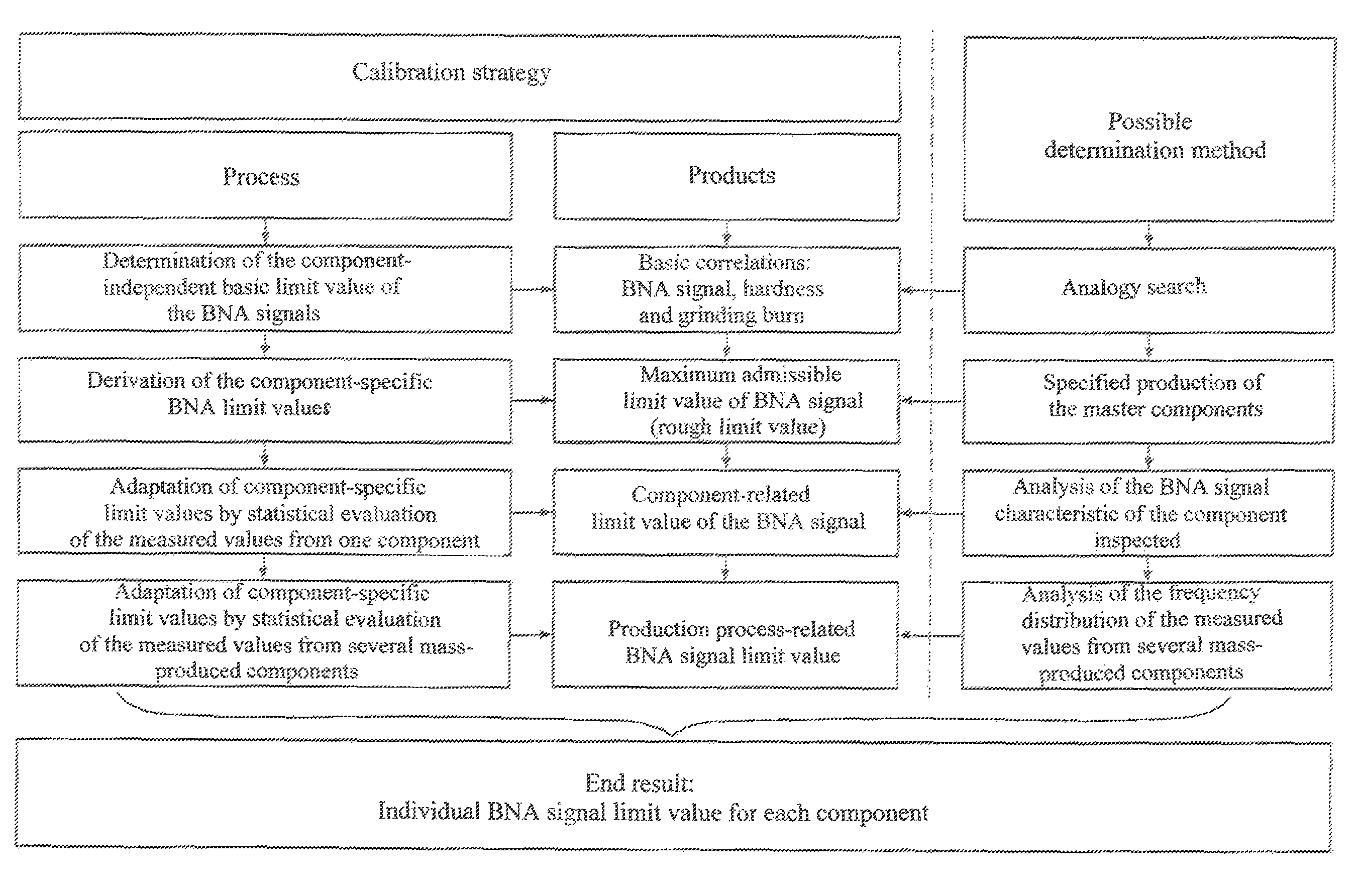
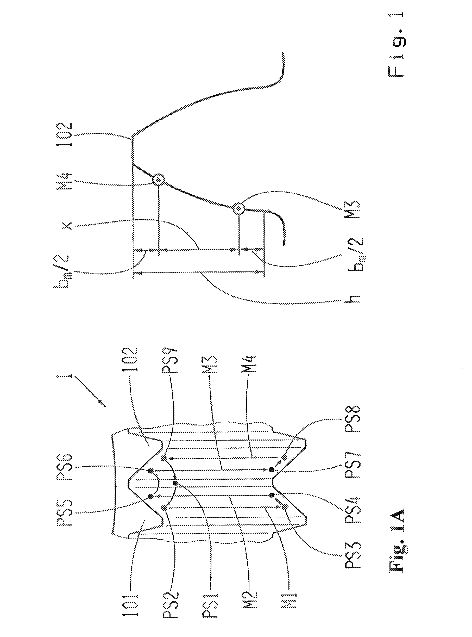
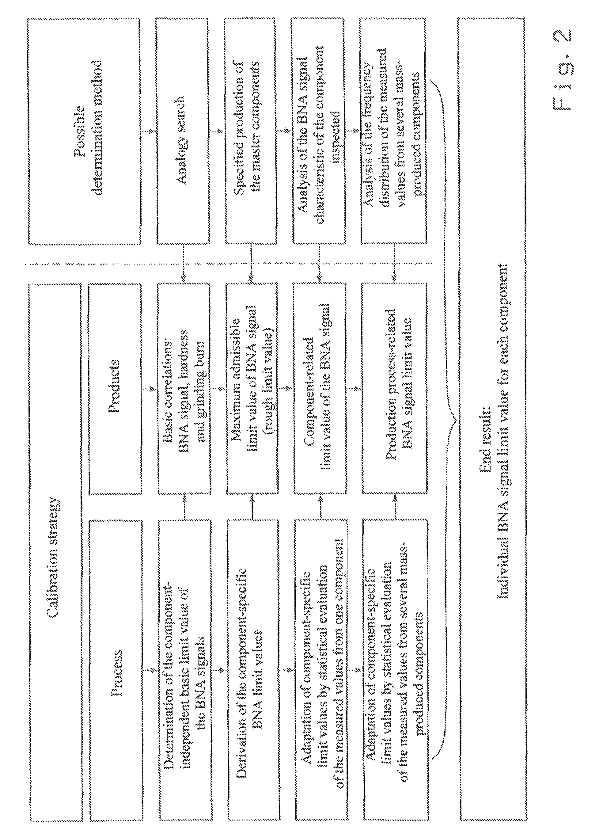

Image

  • Method for calibrating a measuring device for inspecting surfaces on the basis of Barkhausen noises for a specified component geometry
  • Method for calibrating a measuring device for inspecting surfaces on the basis of Barkhausen noises for a specified component geometry
  • Method for calibrating a measuring device for inspecting surfaces on the basis of Barkhausen noises for a specified component geometry

Examples


Embodiment Construction

[0035]Below, the method according to the invention based on a calibration of a measuring device for the surface inspection of components in the form of gearwheels is explained. Nonetheless, the invention can also be used for components of any other type. In the present case, during the manufacture of the gearwheels their final contour is produced by tooth-grinding. During this grinding process the excess material is worn away by grinding grains. This can cause the local temperatures at the contact zone to change so markedly that thermal structural changes take place. These thermal structural changes are often known as grinding burn. It is one objective of the embodiment of the invention described here, by means of an appropriately calibrated measuring device to recognize such components as having surface damaged by grinding burn. Grinding burn is produced, inter alia, if the component-specific annealing temperature is exceeded and occurs in the form of tempering damage as a result o...


PUM

PropertyMeasurementUnit
temperatureaaaaaaaaaa
surface inspectionaaaaaaaaaa
Barkhausen noiseaaaaaaaaaa

Abstract

A method for enhancing inspection of components of specific geometry based on Barkhausen noises. The method includes specifying a first calibration curve that is independent of the component geometry, which describes the relationship between surface hardness values and measured Barkhausen noise signals. A first noise signal is determined by the measuring device for a reference component having the specified geometry and a first hardness value. A second noise signal is determined for a second reference component, having the specified geometry and a second hardness value lower than the first. A second calibration curve is determined, in which the first calibration curve is fitted to the first noise signal at the first hardness value and to the second noise signal at the second hardness value, such that using the second calibration curve, the measured noise signal of a component having the specified geometry relates with a surface hardness value.

Description

[0001]This application is a National Stage completion of PCT / EP2013 / 054229 filed Mar. 4, 2013, which claims priority from German patent application Ser. No. 10 2012 205 676.9 filed Apr. 5, 2012.FIELD OF THE INVENTION[0002]The invention concerns a method for the calibration of a measuring device for surface inspection on the basis of Barkhausen noises for a specific component geometry, and a corresponding measuring device.BACKGROUND OF THE INVENTION[0003]In the industrial production of components, during surface machining damage may occur. Particularly in the mass production of components it is therefore necessary by means of a suitable inspection method to recognize such damage so that the damaged components can be separated out and the production process modified so as to avoid it.[0004]A frequently occurring form of surface damage is the so-termed grinding burn, which for example can take place during tooth grinding to produce the final contour of toothed components. For the recog...

Claims


Application Information

Patent Timeline
Patent Type & Authority Patents(United States)
IPC IPC(8): G01R35/00G01N27/72G01N27/80
CPCG01N27/725G01N27/80G01R35/00
Inventor BLEICHER, OLIVERYAKARIA, HERMANXU, YIWEN
Owner ZF FRIEDRICHSHAFEN AG
Learn More