Catheter, apparatus for creating a linear ablation and a method of ablating tissue

a catheter and linear ablation technology, applied in the field of catheters, can solve the problems of irregularity, slippery, and practical difficulties of surgeons using catheters, and achieve the effects of improving the safety of surgeons, and improving the safety of patients

Active Publication Date: 2016-06-21
PLYMOUTH HOSPITALS NHS TRUST
View PDF21 Cites 1 Cited by
  • Summary
  • Abstract
  • Description
  • Claims
  • Application Information

AI Technical Summary

Benefits of technology

[0011]The present invention provides a catheter for creating a linear ablation on tissue, the catheter having an anchoring member that assists in stabily positioning the catheter with respect to the tissue.
[0018]The present invention also provides a method of ablating tissue, said method comprising: anchoring a linear ablating catheter to said cryogenic catheter; stabily positioning a cryogenic catheter to said tissue via the formation of an ice ball; positioning the rest of the linear ablating catheter to form a linear ablation region on said tissue; and ablating the tissue to form a linear ablation along said linear ablation region.

Problems solved by technology

However, these catheters present practical difficulties to the surgeon in use.
More specifically, the inner wall chambers of the heart, such as the atrial wall, are irregular and slippery and the surgeon encounters a problem in stably positioning the linear catheter in the desired location with sufficient contact at the catheter / tissue surface for the required amount of time to create an effective unbroken line of ablation.
However, this catheter still suffers the problem that it is difficult to position it stabily and accurately due to the deformable nature of the tissue walls.
Such devices have the drawback that the structure can be anchored only in a select few positions where veins exist.
It can be very difficult for the surgeon to create selective ablations at positions far away from the anchoring point in the vein, for example.

Method used


Image

  • Catheter, apparatus for creating a linear ablation and a method of ablating tissue
  • Catheter, apparatus for creating a linear ablation and a method of ablating tissue
  • Catheter, apparatus for creating a linear ablation and a method of ablating tissue

Examples


Embodiment Construction

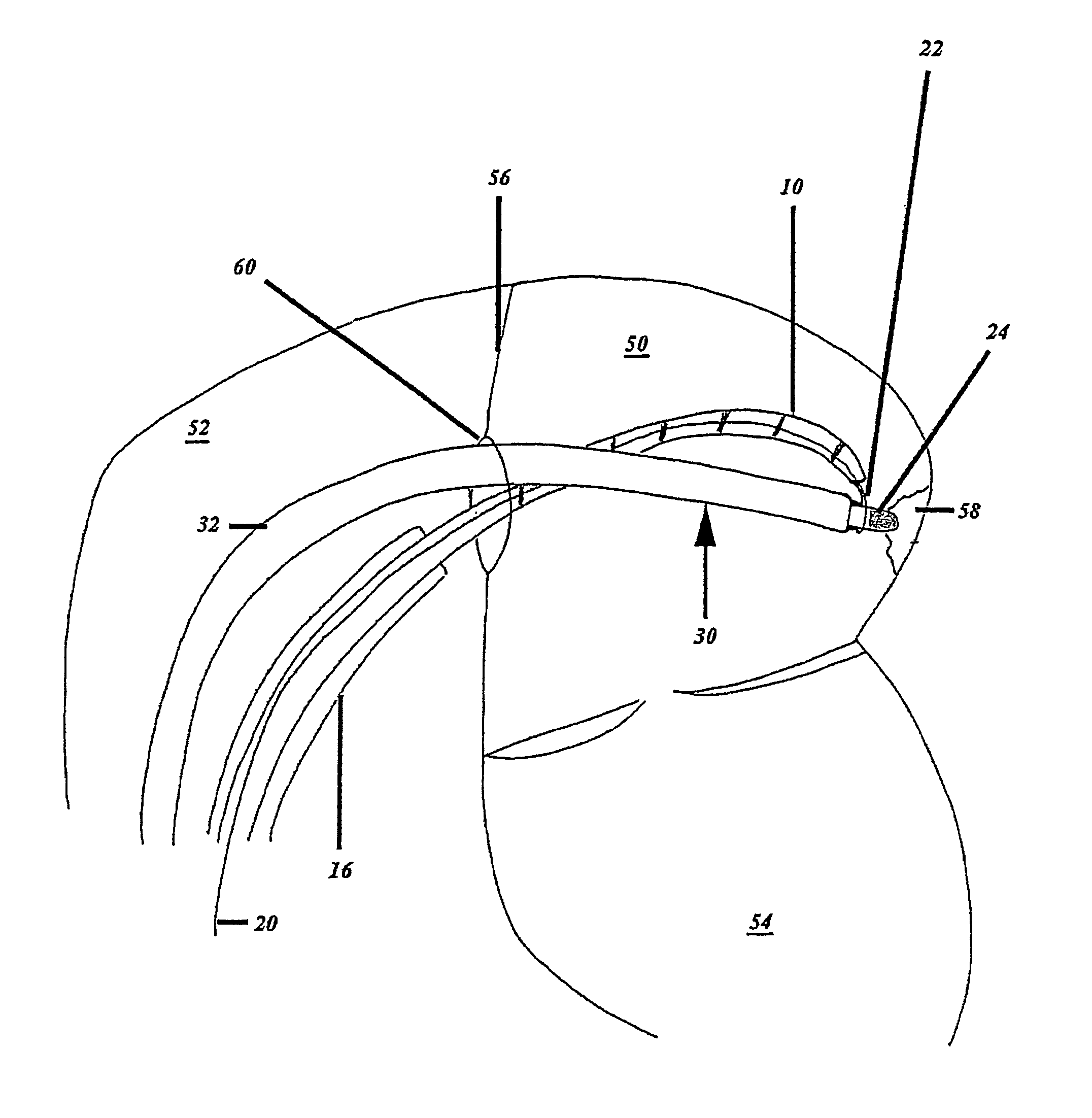
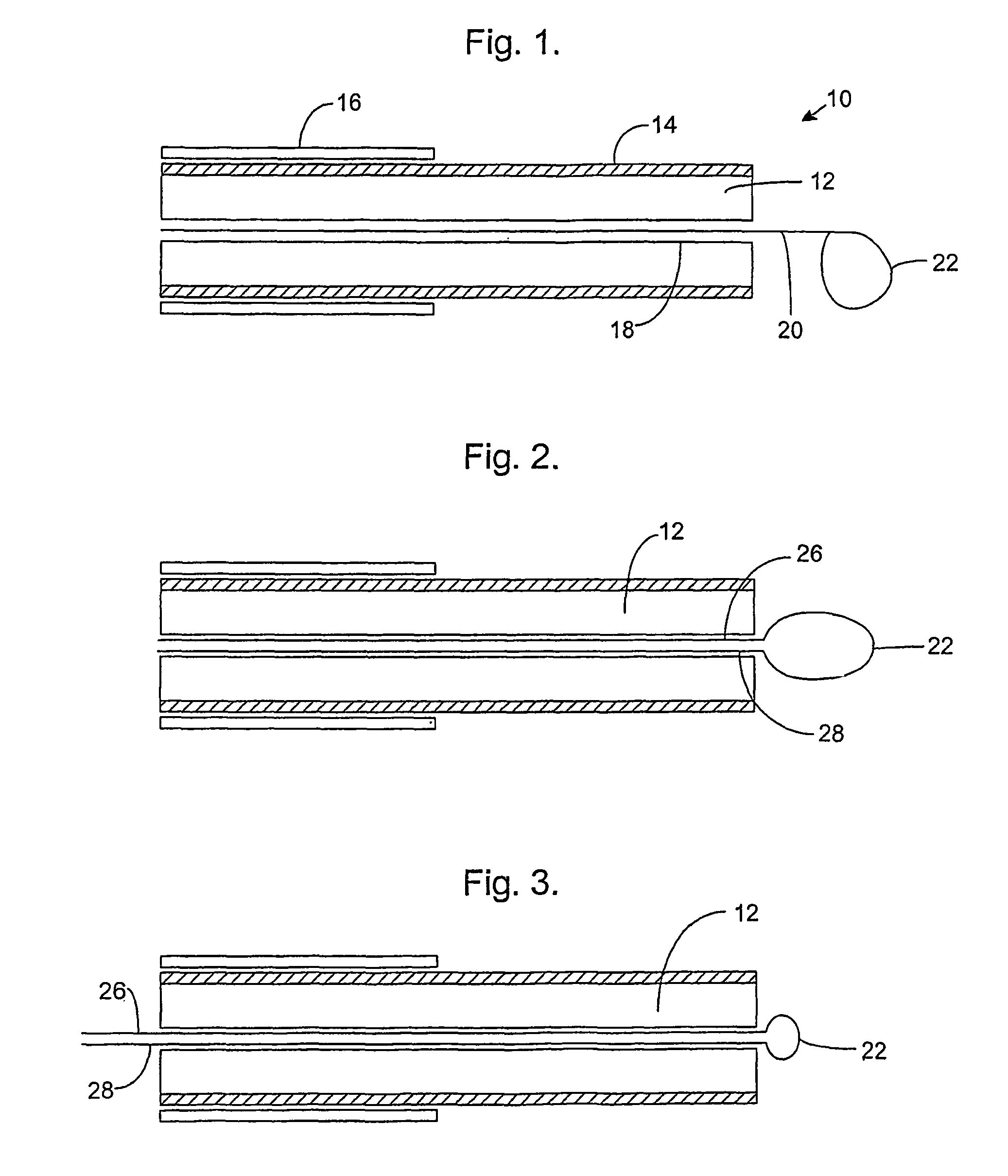
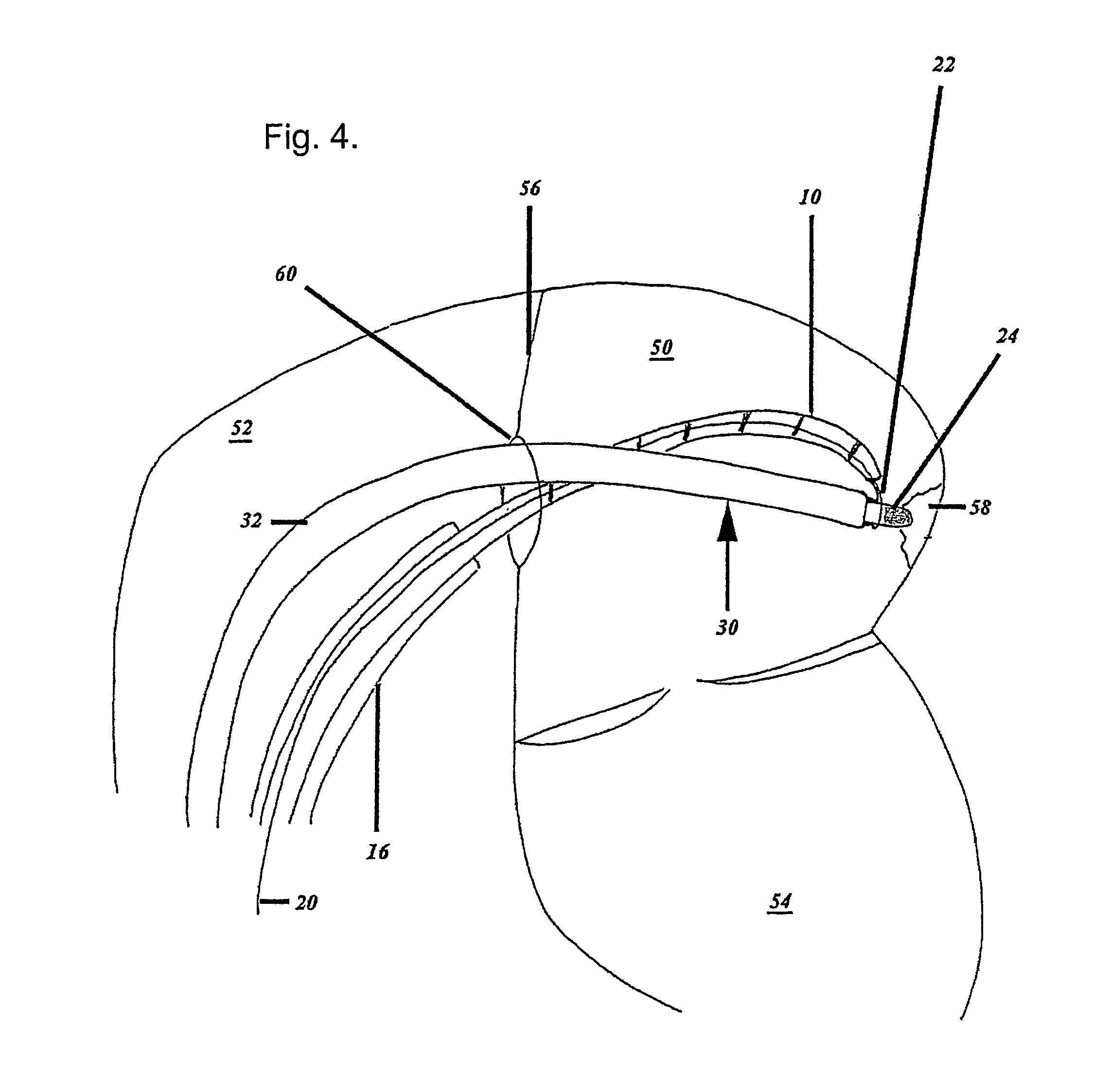
[0029]FIG. 1 is a schematic illustration of a cryosurgical linear catheter 10 in accordance with one aspect of the invention. A cryogenic catheter with a wire loop is discussed merely for the purposes of illustration and other types of linear catheter can be used in practice, with other types of anchoring member, as discussed below. Only the distal part of the catheter is shown in FIG. 1. The catheter comprises a flexible member 12 having a thermally transmissive region 14 and a fluid path (not shown) through the flexible member to the thermally transmissive region. The fluid path is provided between the thermally transmissive region to a point external to the catheter, such as its proximal end (not shown). The thermally transmissive region is the linear ablation section of the catheter which, when in contact with the tissue, causes ablation of that tissue. The thermally transmissive region does not usually extend the whole length of the catheter and is preferably confined to a port...


PUM


Abstract

A catheter is provided with an anchoring member for anchoring a part of a linear ablating head of the catheter to a structure. The structure can be a cryogenically anchored point catheter. This allows the surgeon to position the linear catheter more exactly in the heart chamber and overcomes the adverse effects of the slippery and irregular heart chamber walls.

Description

CROSS-REFERENCE TO RELATED APPLICATIONS[0001]This application is a 371 US National Stage of International Application No. PCT / GB2005 / 002895, filed Jul. 25, 2005. This application claims the benefit of GB Patent Application 0416713.6, filed Jul. 27, 2004. The disclosure of the above applications is incorporated herein by reference.FIELD OF THE INVENTION[0002]The present invention relates to catheters, apparatus comprising catheters and methods of using catheters. The invention more particularly can be applied to a catheter system used for tissue ablation in the heart.BACKGROUND OF THE INVENTION[0003]Many medical procedures are performed using minimally invasive surgical techniques, wherein one or more slender implements are inserted through one or more small incisions into a patient's body. With respect to ablation, the surgical implement can include a rigid or flexible structure having an ablation device at or near its distal end that is placed adjacent to the tissue to be ablated. ...

Claims


Application Information

Patent Timeline
Patent Type & Authority Patents(United States)
IPC IPC(8): A61B18/14A61B18/02A61B18/00
CPCA61B18/02A61B18/1492A61B2018/00273A61B2018/0212
Inventor HAYWOOD, GUY
Owner PLYMOUTH HOSPITALS NHS TRUST
Why Eureka
Try Eureka