System with 3D user interface integration

a user interface and system technology, applied in the field of system with 3d user interface integration, can solve the problems of inconvenient use, inconvenience, awkwardness, etc., and achieve the effect of more flexibly exploiting

Active Publication Date: 2016-05-03
3SHAPE AS
View PDF22 Cites 33 Cited by
  • Summary
  • Abstract
  • Description
  • Claims
  • Application Information

AI Technical Summary

Benefits of technology

[0016]It is thus an advantage of the present system that the 3D user-interface functionality is integrated in the central device, which is used for performing some kind of action.
[0099]An advantage of the system, also in the above surgery example, is the ability of the handheld device to record the 3D environment at least partially, typically in a 3D field-of-view that is smaller than the volume represented in the a-priori data. The 3D data recorded by the handheld device can be registered in real time with the a-priori data, such that the position and orientation of the device can be detected.

Problems solved by technology

Displaying and inspecting 3D information is inherently difficult.
Physically touching a user-interaction device can be a disadvantage in medical applications due to risks of cross-contamination between patients or between patient and operator, or in industrial applications in dirty environments.
It remains a problem to improve systems that require user interfaces for view control, which for example can be used for clinical purposes.
These prior art user interface devices can be inconvenient, awkward and difficult to use, and they can be labor-intensive, and thus costly to sterilize or disinfect.
However, in some cases it may not be possible for the operator to fully avoid touching other devices, and in these cases it is an advantage that fewer touches are required compared to a system where a handheld device does not provide any user interface functionality at all.
Especially in crowded environments such as dentist's clinics, surgical operation theatres, or industrial workplaces, it may be difficult to place an external display closely to the device.
The Lava C.O.S scanner marketed by 3M ESPE has additional buttons on the handheld device, but it is not possible to manipulate the view by these.
Thus, in some embodiments the user interface functionality comprises virtual user interface functionality, which can be that the 3D data are manipulated, but the physical 3D environment in which the device operates may not be manipulated.

Method used


Image

  • System with 3D user interface integration
  • System with 3D user interface integration
  • System with 3D user interface integration

Examples


embodiments

[0151]The following embodiments relates to one aspect of the system as disclosed by the description herein.

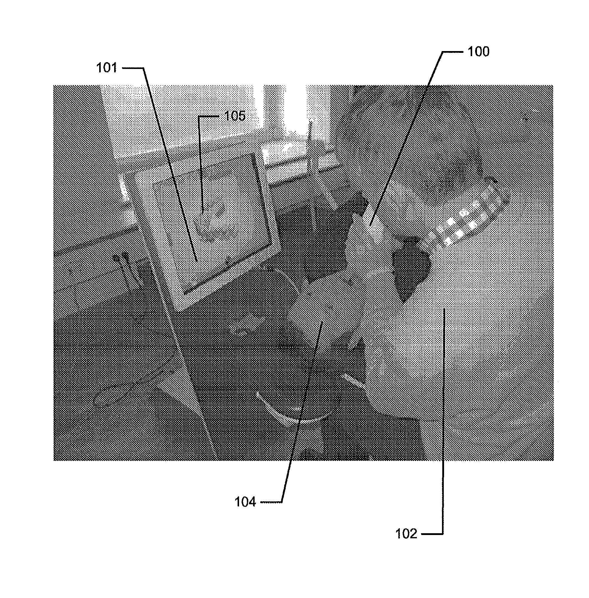
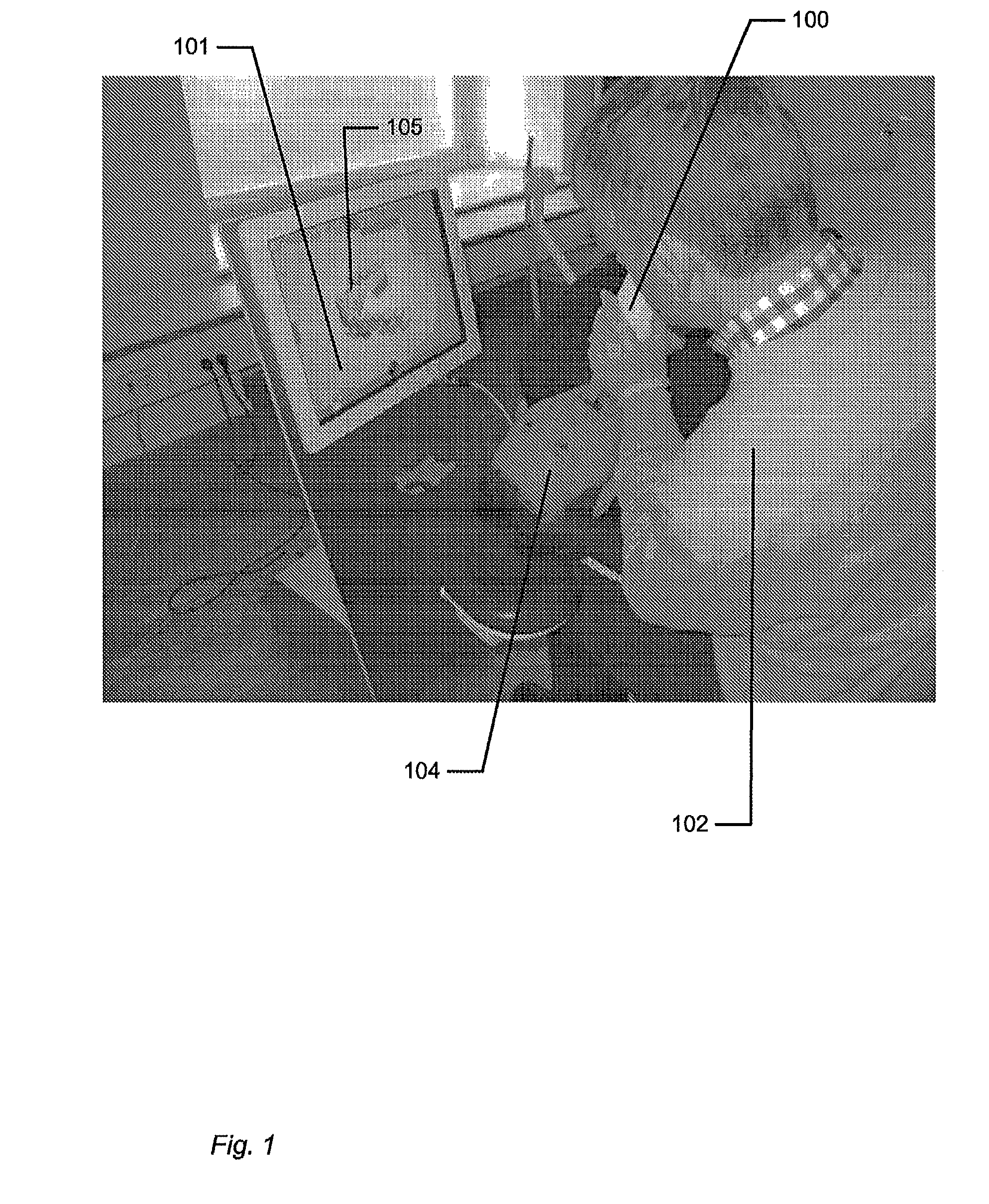
[0152]1. A system comprising a handheld device and at least one display, where the handheld device is adapted for performing at least one action in a physical 3D environment, where the at least one display is adapted for visually representing the physical 3D environment, and where the handheld device is adapted for remotely controlling the view with which the 3D environment is represented on the display.

[0153]2. The system according to any one or more of the preceding embodiments, wherein the view is defined as viewing angle and / or viewing position.

[0154]3. The system according to any one or more of the preceding embodiments, wherein the handheld device is adapted for remotely controlling the magnification with which the 3D environment is represented on the display.

[0155]4. The system according to any one or more of the preceding embodiments, wherein the handheld device is adap...


PUM


Abstract

Disclosed is a system comprising a handheld device and at least one display. The handheld device is adapted for performing at least one action in a physical 3D environment; wherein the at least one display is adapted for visually representing the physical 3D environment; and where the handheld device is adapted for remotely controlling the view with which the 3D environment is represented on the display.

Description

FIELD OF THE INVENTION[0001]This invention generally relates to a method and a system comprising a handheld device and at least one display.BACKGROUND OF THE INVENTION[0002]3D visualization is important in many fields of industry and medicine, where 3D information is becoming more and more predominant.[0003]Displaying and inspecting 3D information is inherently difficult. To fully understand a 3D object or entire environment on a screen, the user should generally be able to rotate the object or scene, such that many or preferentially all surfaces are displayed. This is true even for 3D displays, e.g. stereoscopic or holographic, where from a given viewing position and with a given viewing angle, the user will only see some surfaces of an arbitrary 3D environment. Often, the user will also want to zoom into details or zoom out for an overview.[0004]Various user interaction devices are in use for software that displays 3D data; these devices are: 3D mice, space balls, and touch screen...

Claims


Application Information

Patent Timeline
Patent Type & Authority Patents(United States)
IPC IPC(8): G06F3/01A61C9/00G01B11/24
CPCA61C9/004G01B11/24G06F3/04815A61B5/0088G06F3/017G06F3/0346G06F3/002G06F3/011G06F3/01
Inventor OJELUND, HENRIKFISCHER, DAVIDHOLLENBECK, KARL-JOSEF
Owner 3SHAPE AS
Why Eureka
Try Eureka