
Tool box

a tool box and tool box technology, applied in the field of tool boxes, can solve the problems of inconvenient use for users, easy breakage of the thin plate, and tool box tools suddenly falling from the tool box

Inactive Publication Date: 2016-01-12
LAI CHIA WEI
View PDF26 Cites 34 Cited by
  • Summary
  • Abstract
  • Description
  • Claims
  • Application Information

AI Technical Summary

Benefits of technology

The present invention provides a tool box with two hinges that do not loose between the base and the cover. This feature helps to improve the durability and reliability of the tool box.

Problems solved by technology

However, the thin plate is easily broken after frequent open-and-close actions, and the tools in the tool box may suddenly drop from the tool box.
This is not convenient for the users.

Method used


Image

  • Tool box
  • Tool box
  • Tool box

Examples


Embodiment Construction

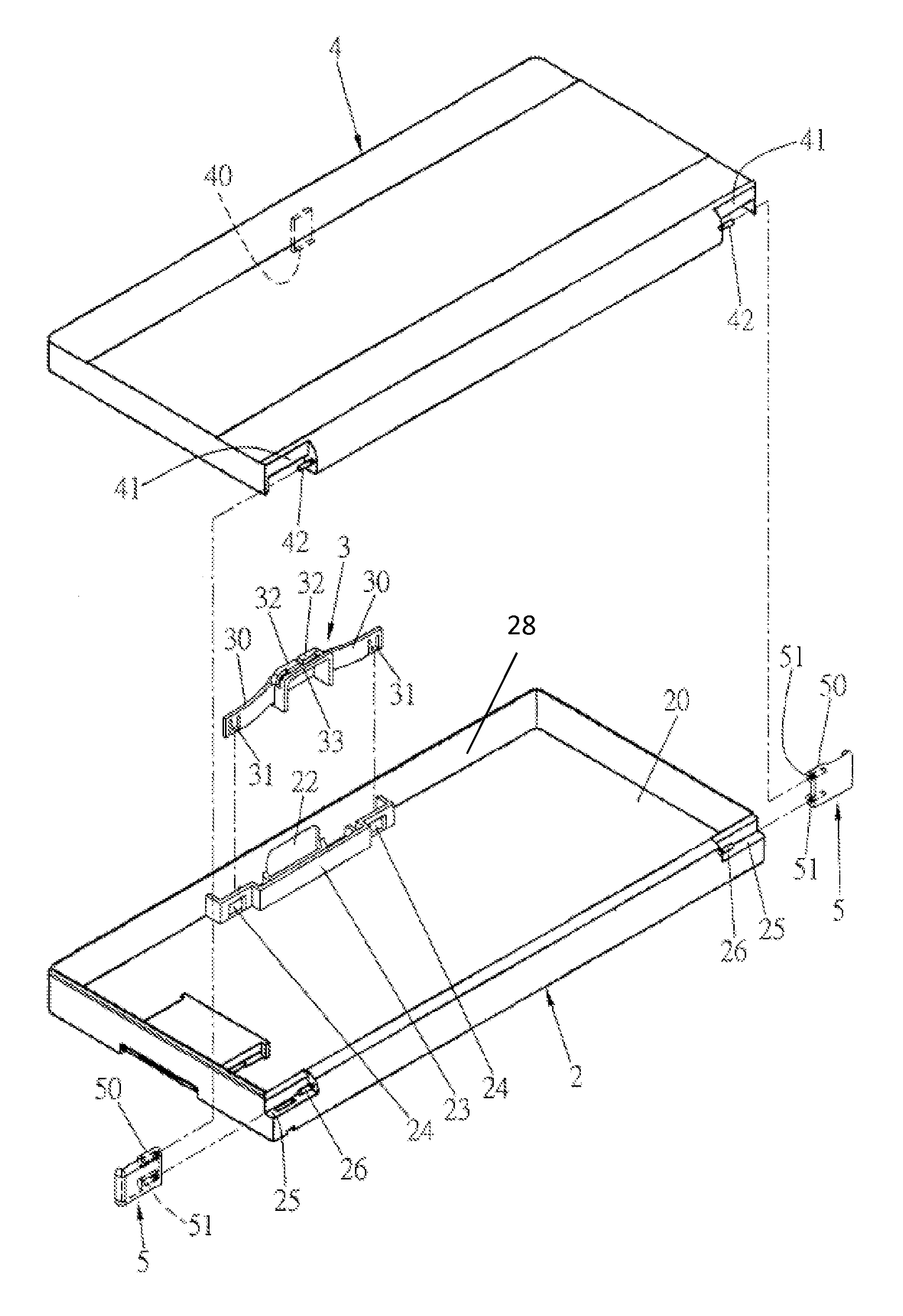
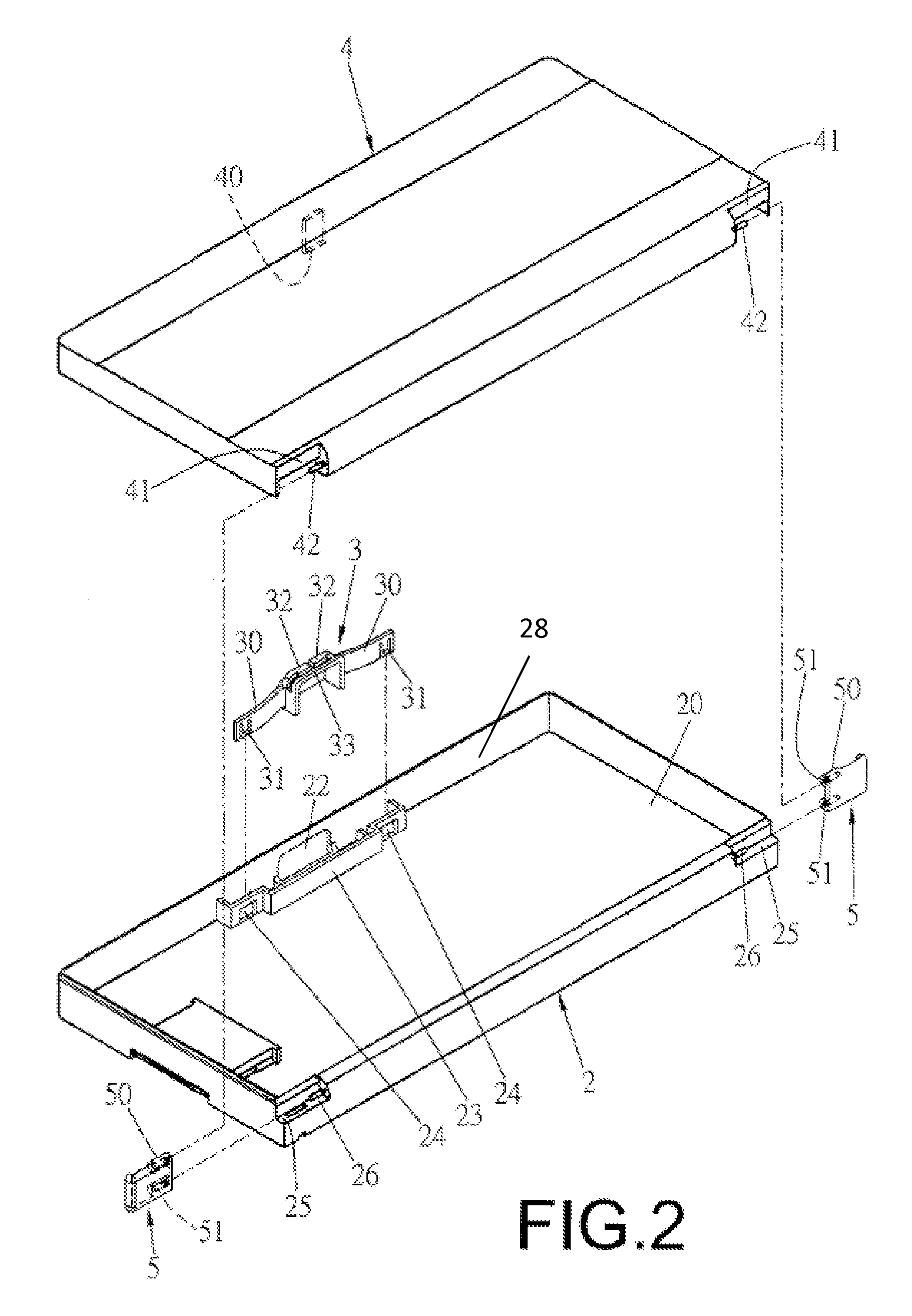
[0026]Referring to FIGS. 2 to 4, the tool box of the present invention comprises a base 2 having a space 20 defined therein so as to receive tools in the space 20. A recessed area 21 is defined in the first side of the base 2 and a through hole 22 is defined through an upright wall 28 of the first side of the base 2. A fixing member 23 is connected to the inside of the upright wall 28 of the first side of the base 2 and located corresponding to the recessed area 21. Two positioning holes 24 are defined through the fixing member 23. The base 2 has two first recesses 25 defined in two ends of the second side thereof and each of the first recesses 25 has a pivot 26 located therein. Each of the pivots 26 has a lip 27 extending radially and outward therefrom as shown in FIG. 4.

[0027]A button 3 is located in the recessed area 21 and connected to the fixing member 23. The button 3 has a resilient arm 30 extending from each of two ends thereof, and each resilient arm 30 has a protrusion 31 ...


PUM


Abstract

A tool box includes a base, a button, a cover and two hinges. The button is located in a recessed area of the base and connected to a fixing member that is connected to the recessed area. The button has a resilient arm extending from each of two ends thereof, and each resilient arm has a protrusion which is engaged with the positioning hole of the fixing member. Two resilient piece extending toward each other from the top edge thereof and a flange extends from one side of the button. The cover is pivotably connected to the base by the two hinges. The cover has a locking member so as to be engaged with the flange of the button. The two resilient piece push the cover upward when the cover is unlocked from the base. The hinges are not loosened after frequent use.

Description

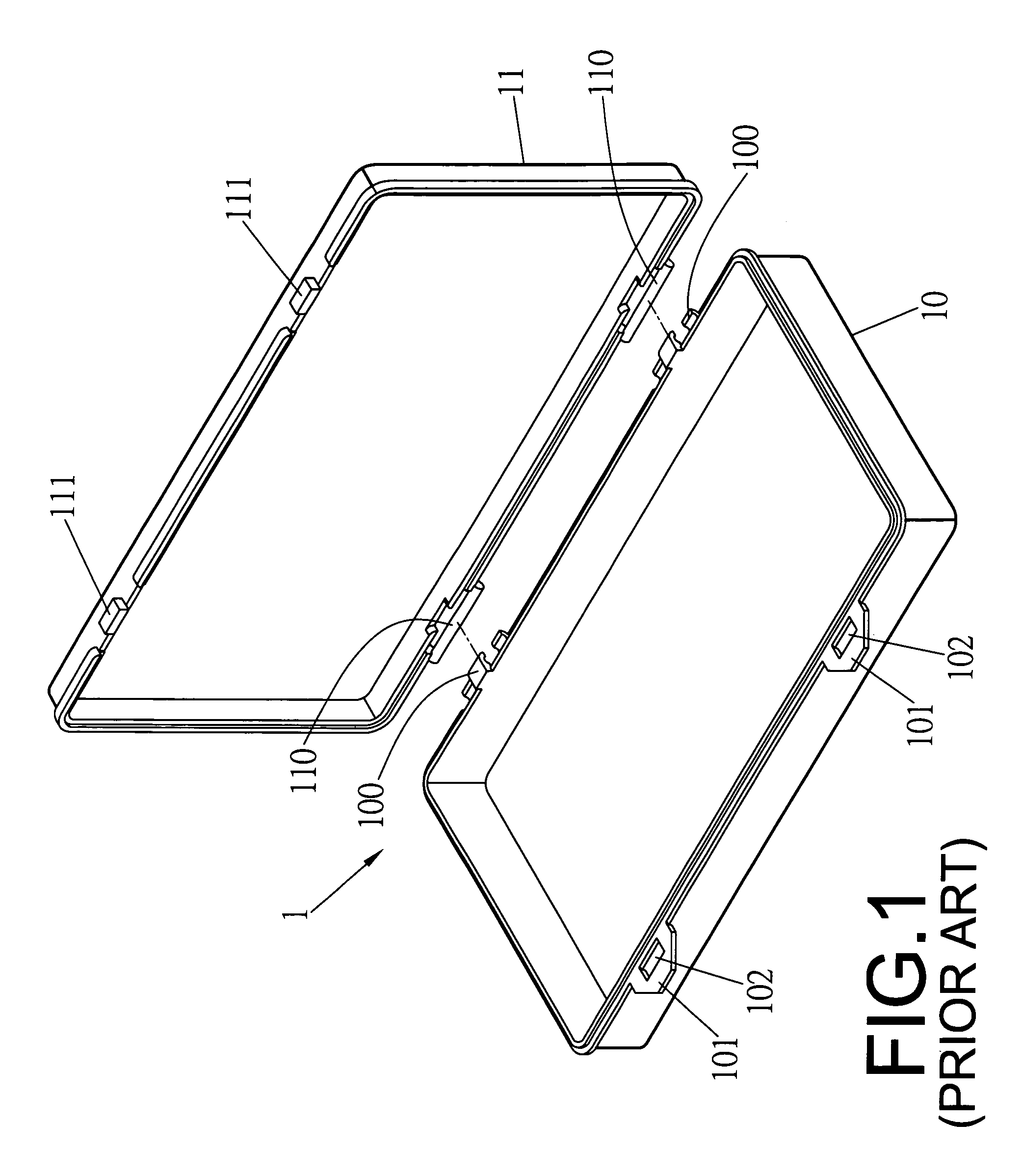
BACKGROUND OF THE INVENTION[0001]1. Fields of the Invention[0002]The present invention relates to a tool box, and more particularly, to a tool box wherein the cover slightly pops when the locking member is released.[0003]2. Descriptions of Related Art[0004]The conventional tool box generally comprises a base and a cover which is pivotably connected to one side of the base by a thin plate. The other side of each of the base and the cover has a locking member so as to lock the cover to the base. However, the thin plate is easily broken after frequent open-and-close actions, and the tools in the tool box may suddenly drop from the tool box.[0005]Another conventional tool box 1 is disclosed in FIG. 1 and generally comprises a base 10 and a cover 11 wherein the base 10 has pivotal members 100 on one side thereof. The cover 11 has pivots 110 on one side thereof. The pivots 110 pivotably extend through the pivotal members 100 to pivotably connect the base 10 to the cover 11. The other side...

Claims


Application Information

Patent Timeline
Patent Type & Authority Patents(United States)
IPC IPC(8): B65D85/28B65D55/02B65D43/16B25H3/02
CPCB25H3/02B65D43/164B65D55/02
Inventor LAI, CHIA, WEI
Owner LAI CHIA WEI
Learn More