
Drainage tube insertion tool

a technology of insertion tool and draining tube, which is applied in the field of draining tube insertion tool, can solve the problems of not allowing the use of conventional techniques, and achieve the effect of preventing the pusher tube from coming

Active Publication Date: 2015-09-29
FUJIFILM CORP
View PDF5 Cites 0 Cited by
  • Summary
  • Abstract
  • Description
  • Claims
  • Application Information

AI Technical Summary

Benefits of technology

[0008]According to the present invention, it is possible to insert the drainage tube in a target constricted region by pushing the drainage tube with the pusher tube while using the outer surface of the insertion portion of the endoscope as a guide. In addition, although the pusher tube cannot be fitted on the insertion portion from the proximal end side due to the structure of the endoscope, it is possible to fit the pusher tube on the insertion portion from the side surface owing to the notch formed in the pusher tube without fitting the pusher tube on the insertion portion from the distal end side. This makes it possible to fit the pusher tube on the insertion portion even after the insertion of the insertion portion into the body cavity. That is, the pusher tube does not interfere with the insertion of the insertion portion into a predetermined region in the body cavity.
[0014]According to the present invention, it is possible to insert and indwell a drainage tube in a desired constricted region by using the insertion portion of an endoscope as a guide member without making the drainage tube pass through the treatment tool insertion channel of the insertion portion.

Problems solved by technology

Such endoscope has a treatment tool insertion channel whose inner diameter is small, and hence does not allow to use the conventional technique of inserting the guide tube into the biliary tractor or pancreatic duct through the treatment tool insertion channel.
In addition, although the pusher tube cannot be fitted on the insertion portion from the proximal end side due to the structure of the endoscope, it is possible to fit the pusher tube on the insertion portion from the side surface owing to the notch formed in the pusher tube without fitting the pusher tube on the insertion portion from the distal end side.

Method used


Image

  • Drainage tube insertion tool
  • Drainage tube insertion tool
  • Drainage tube insertion tool

Examples


Embodiment Construction

[0027]A preferred embodiment of the present invention will be described in detail below with reference to the accompanying drawings.

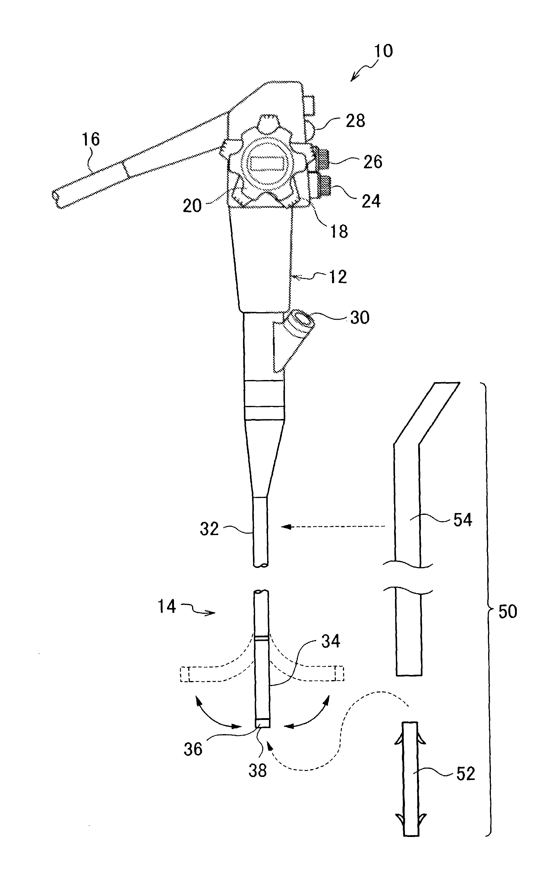
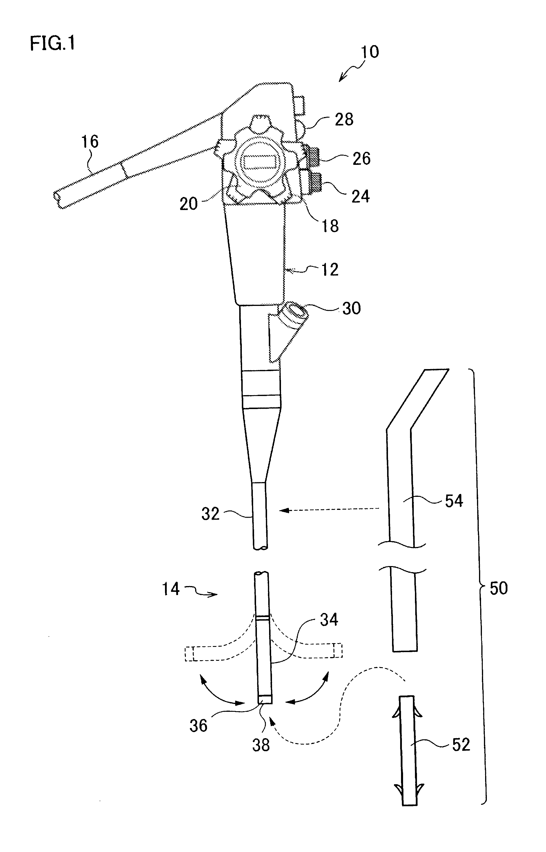
[0028]FIG. 1 is an overall view showing an embodiment of an endoscope to which a drainage tube insertion tool according to the present invention and a drainage according to the present invention are applied. An endoscope 10 in FIG. 1 is an endoscope used as a cholangioscope for observing mainly the lumen of the biliary tractor or pancreatic duct (pancreatic-bile system). The endoscope 10 includes an operation portion 12, an insertion portion 14 which is connected in series with the operation portion 12 and inserted into the body cavity, and a universal cable 16 extending from the operation portion 12. At the time of medical treatment, the endoscope 10 is used while being connected to an image processor, light source device, air / water supply device, and suction device (none of which are shown) through the universal cable 16.

[0029]The operation portion 12...


PUM


Abstract

A drainage tube insertion tool for use in an endoscope, comprising:a drainage tube configured to slidably fit on an outer surface of an insertion portion of the endoscope, anda pusher tube configured to slidably fit on the outer surface of the insertion portion of the endoscope and which pushes the drainage tube,wherein a notch is formed in a side wall portion of the pusher tube along a longitudinal axis direction, and the pusher tube is fitted on the outer surface of the insertion portion upon making a side surface of the insertion portion extend through the notch, and the drainage tube is inserted into a predetermined lumen of a body cavity by pushing the drainage tube out of a distal end of the insertion portion with the pusher tube.

Description

BACKGROUND OF THE INVENTION[0001]1. Field of the Invention[0002]The present invention relates to a drainage tube insertion tool and, more particularly, to a drainage tube insertion tool for inserting and indwelling a drainage tube in the biliary tract or the pancreatic duct.[0003]2. Description of the Related Art[0004]Conventionally, in order to drain bile retained in the biliary tract or pancreatic juice retained in the pancreatic duct into the duodenum, a drainage tube is inserted and indwelled in a constricted region of the biliary tract or pancreatic duct. As a technique of indwelling the drainage tube in the biliary tractor or pancreatic duct, for example, there is available a technique of inserting the insertion portion of a side-viewing endoscope into a portion near the papilla vater of the duodenum, and inserting a guide wire from the papilla vater into the biliary tractor or pancreatic duct through the treatment tool insertion channel of the insertion portion. Then, a guide...

Claims


Application Information

Patent Timeline
Patent Type & Authority Patents(United States)
IPC IPC(8): A61B1/00A61B1/04A61F2/06A61B1/015
CPCA61B1/015A61B1/00073A61B1/00135
Inventor HIRANO, SOTAOHKI, TOMOHIRO
Owner FUJIFILM CORP
Learn More