Eureka AIR delivers breakthrough ideas for toughest innovation challenges, trusted by R&D personnel around the world.

Examination apparatus

a technology of apparatus and test tube, applied in the field of test tube, can solve the problems of reducing the performance and concentration of users during the intervention

Inactive Publication Date: 2015-08-18
KONINK PHILIPS ELECTRONICS NV
View PDF22 Cites 177 Cited by
  • Summary
  • Abstract
  • Description
  • Claims
  • Application Information

AI Technical Summary

Benefits of technology

[0004]There may exist a need to improve the visual reception of information relating to the object.
[0068]This allows providing additional information to the user which is not shown on the image data displayed by the display unit but which is of crucial importance to the performance of the intervention by the user.

Problems solved by technology

But it has shown that due to an increasing number of parameters that can be displayed to provide information about the object of interest, for example the patient, the user sometimes experiences a fatigue that leads to a decrease in the user's performance and concentration during the intervention.

Method used


Image

  • Examination apparatus
  • Examination apparatus
  • Examination apparatus

Examples


Embodiment Construction

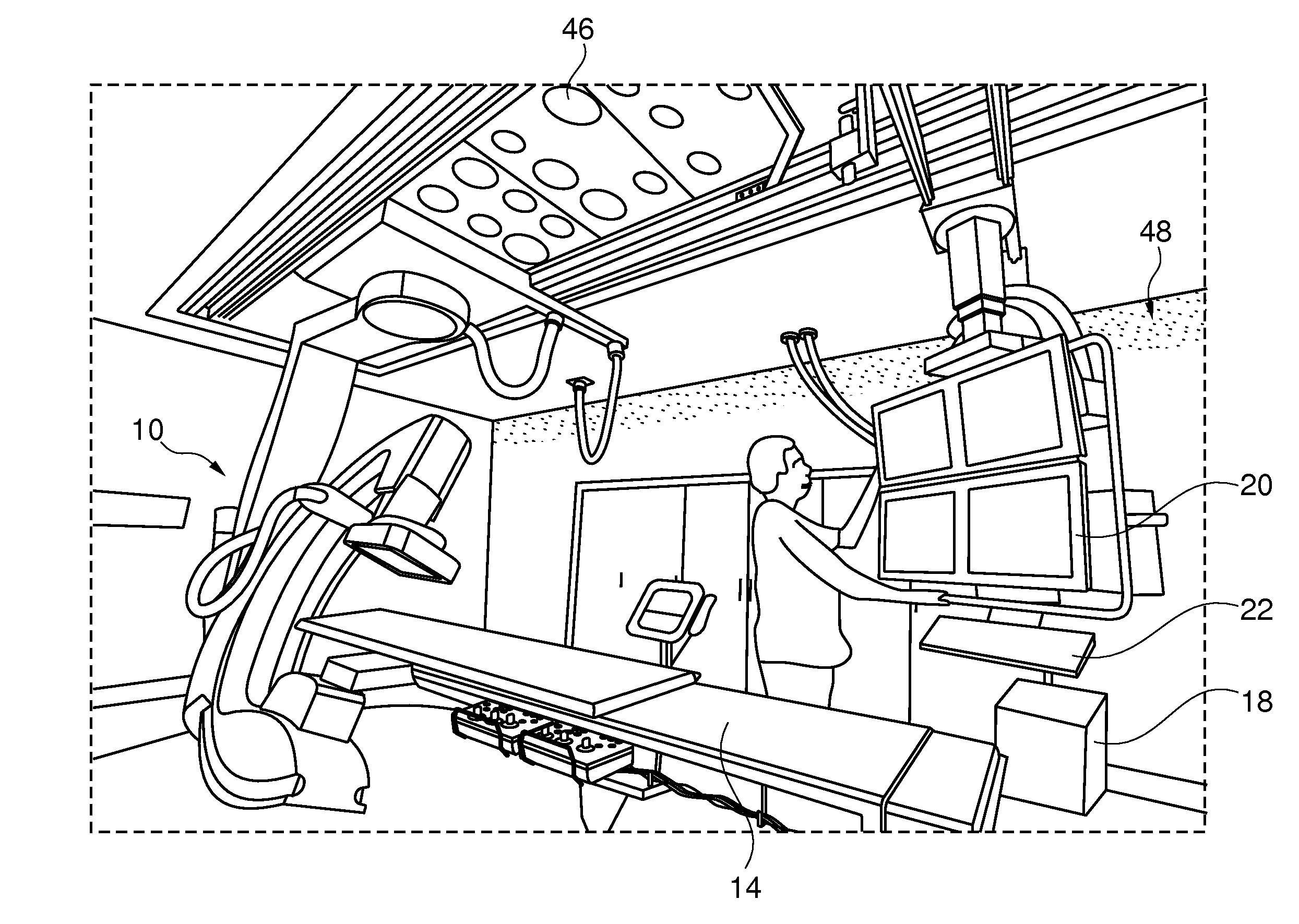
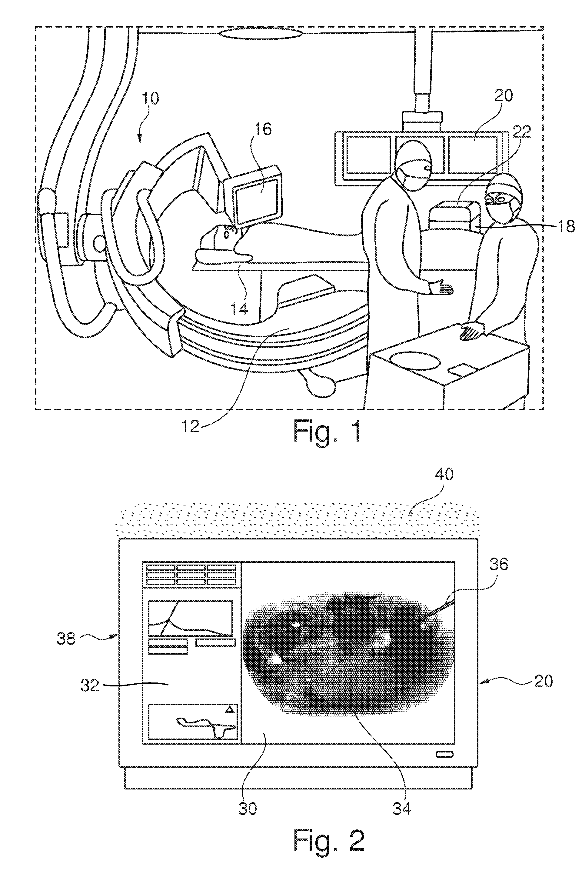
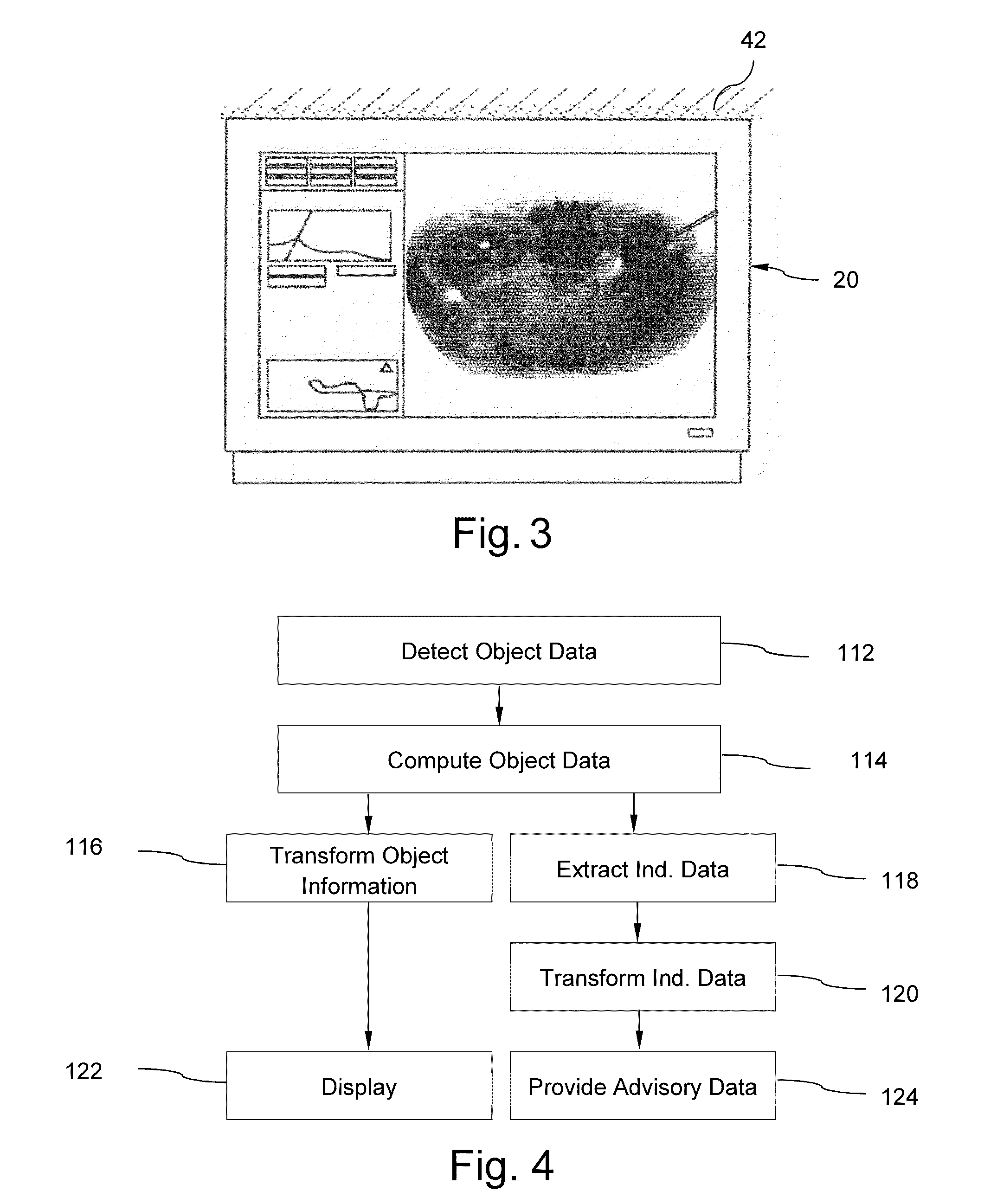
[0093]FIG. 1 schematically shows an X-ray suite with an examination apparatus comprising an X-ray imaging system 10 for the use in an intervention laboratory of a hospital, for example. The X-ray imaging system 10 comprises an X-ray image acquisition device with a source of X-ray radiation 12 provided to generate X-radiation. A table 14 is provided to receive a subject to be examined, for example a patient. Further, an X-ray detection module 16 is located opposite the source of X-ray radiation 12, i.e. during the radiation procedure, the subject is located between the source of X-ray radiation 12 and the detection module 16. The latter is sending data to a data processing unit or control unit 18, which is connected to both the detection module 16 and the radiation source 12. The calculation or control unit 18 is located in the vicinity of the table 14 or can also be located underneath the table 14 to save space within the laboratory. Of course, it could also be located at a differen...


PUM

PropertyMeasurementUnit
optical spectroscopicaaaaaaaaaa
surface areaaaaaaaaaaa
areaaaaaaaaaaa

Abstract

The present invention relates to an examination apparatus for providing information about an object and a method for providing information about an object of interest. In order to improve the visual reception of information relating to the object, an examination apparatus is provided that comprises an examination arrangement and a control unit with at least a first interface and a second interface. The examination arrangement is adapted to detect object data from at least one region of interest of an object and to provide the object data to the control unit. Further, the control unit is adapted to compute object data into object information and to transform at least a part of the object information into image data (32, 36). Further, the control unit is arranged to extract pre-determined indicative data from the object information and to transform the indicative data into graphical advisory data (40). The first interface is configured such to provide the image data to a display unit (20) in order to display the image data (32, 36) to the user. The second interface is configured such to provide a signal for an ambient advice display arrangement in order to provide the graphical advisory data (40) to the user.

Description

FIELD OF THE INVENTION[0001]The present invention is related to an examination apparatus for providing information about an object and a method for providing information about an object of interest.BACKGROUND OF THE INVENTION[0002]Information about an object can be required, for example, during an intervention to provide necessary or desired knowledge of the object in order to be able to perform further interventional steps. This knowledge can serve as a sort of feedback, for example in cases where the results of the intervention are difficult to detect, such as in cases where the object of interest is a patient, where medical intervention can be performed in such a way that the actual interventional process or even the result cannot be detected by the person performing the intervention. It is therefore known for example, to provide display screens or monitors during interventions, such as surgical interventions, where information about the state of a target area is shown in still i...

Claims


Application Information

Patent Timeline
Patent Type & Authority Patents(United States)
IPC IPC(8): G01N23/04A61B17/34H05G1/08A61B6/12H05B33/08G06F19/00A61B6/00A61B17/00A61B19/00H05B44/00
CPCA61B17/3403A61B6/12A61B6/463A61B6/464A61B6/467A61B19/56G06F19/321H05B33/0803A61B19/5202A61B2017/00035A61B2017/00061A61B2017/00084A61B2017/00128A61B2019/507A61B2019/5229A61B2019/5238A61B2019/564A61B2034/254A61B90/30A61B34/25A61B2090/376A61B2034/107A61B2090/372G16H30/20G16H30/40
Inventor HENDRIKS, BERNARDUS HENDRIKUS WILHELMUSDESJARDINS, ADRIEN EMMANUELMCKINNEY, MARTIN FRANCISCUS
Owner KONINK PHILIPS ELECTRONICS NV
Why Eureka
Eureka Blog
Learn More