
Functional table for transferring patient

a technology for transferring patients and tables, which is applied in the direction of wheelchairs/patient conveyance, patient positioning for diagnostics, branching pipes, etc., can solve the problems of secondary damage may occur if the assistants miss the stretcher, and patients who cannot be moved at all, so as to achieve ease, safety and promptness, and without the risk of secondary damage to patients

Inactive Publication Date: 2015-05-12
IND ACADEMIC COOPERATION FOUND KEIMYUNG UNIV
View PDF84 Cites 1 Cited by
  • Summary
  • Abstract
  • Description
  • Claims
  • Application Information

AI Technical Summary

Benefits of technology

Enables safe, easy, and prompt transportation of patients between medical tables without risking secondary damage, reducing the need for multiple assistants and minimizing patient movement, thus improving the safety and efficiency of patient transfers.

Problems solved by technology

However, there is a problem in moving the patient from the hospital bed to the stretcher or the patient transporting bed.
For example, although it is a simple task to move the patient in support of the assistant if the patient is cooperative or can move for himself, there may be a challengeable task to move the patient from the hospital bed to the stretcher or the patient transporting bed if the patient is unconscious or has a damage such as a bone-fracture or an injury, which may be worsened by movement.
However, this has a problem in that it requires two assistants who have to lift the stretcher from its both sides when the patient is transported from one bed to another, and the weight of the stretcher to support the patient is still the same.
In addition, a secondary damage may occur if the assistants miss the stretcher.
Moreover, there is a further problem that a patient who cannot be moved at all has to receive help from at least another assistant in order to transport and safely lay the patient on another table.

Method used


Image

  • Functional table for transferring patient
  • Functional table for transferring patient
  • Functional table for transferring patient

Examples


Embodiment Construction

[0025]Hereinafter, preferred embodiments of the present invention will be described in detail with reference to the accompanying drawings.

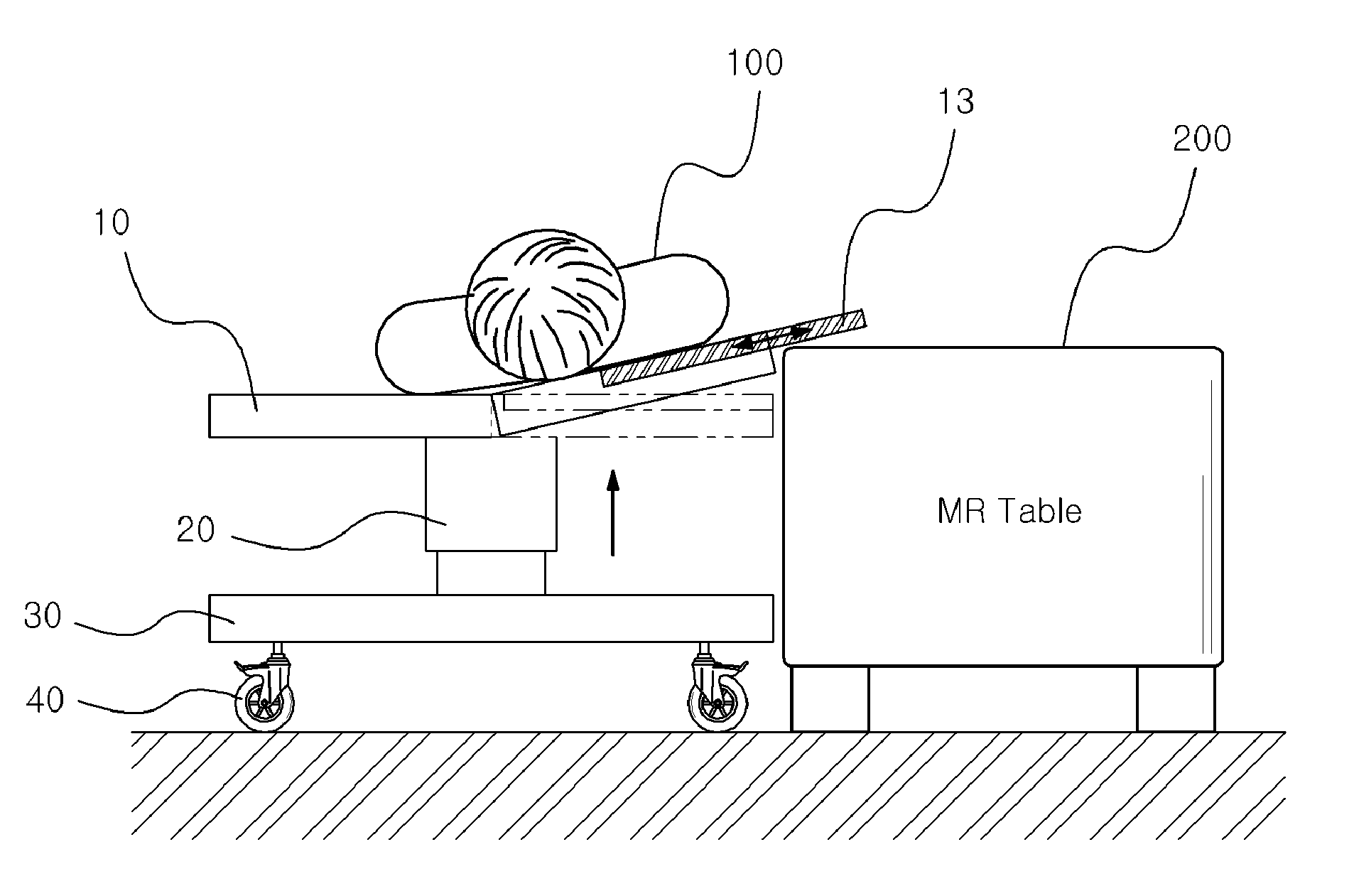
[0026]FIG. 1 is a view illustrating a side of a functional table for patient transportation according to an embodiment of the present invention. As shown in FIG. 1, a functional table of the present invention includes a patient supporter to support a patient 100 (see FIG. 4), a vertically-movable support frame 20 to support the patient supporter 10, a base frame 30 which is connected to the bottom of the support frame 20 and supports the whole of functional table, and transporting wheels 40 which are connected to the bottom of the base frame 30 to allow the functional table to be freely moved in every direction.

[0027]In this manner, the functional table of the present invention is so configured that the patient supporter 10 on which the patient 10 is laid can be adjusted in its height by the vertically-movable support frame 20 connected to the cen...


PUM


Abstract

The present invention relates to a functional table for patient transportation, including: a patient supporter which supports a patient laid thereon and allows the patient to be horizontally slidably transported, with its both sides being changed in their angle with respect to a vertical axis of the patient; a support frame which is located in the central bottom of the patient supporter and allows the patient supporter to be vertically moved; a base frame which is connected to the bottom of the support frame and supports the whole of functional table; and at least three transporting wheels which are connected to the base frame and allow the functional table to be freely moved.

Description

TECHNICAL FIELD[0001]The present invention relates to a functional table for patient transportation, and more particularly, to a functional table for patient transportation which is capable of transporting patients with safety, ease and promptness without a risk of secondary damage to the patients.BACKGROUND ART[0002]As known in the art, there has been proposed a variety of apparatuses for transporting emergency patients, critical patients, bone-fracture patients and the like, who are impossible or nearly impossible to move for themselves, from one place to another.[0003]A patient in a hospital may be often moved from his / her hospital bed to a medical examination table or an operating table and vice versa. Primary equipment may include a stretcher carried by an assistant and a patient transporting bed with wheels.[0004]However, there is a problem in moving the patient from the hospital bed to the stretcher or the patient transporting bed. For example, although it is a simple task to...

Claims


Application Information

Patent Timeline
Patent Type & Authority Patents(United States)
IPC IPC(8): A47B13/00A61G7/10F16M13/00F16D1/00A47C21/00A61F5/37A61B6/04A61G7/012
CPCA61G7/103A61G7/1036A61B6/04A61G7/012Y10T403/32426Y10T403/346Y10T403/59Y10T403/602F16B2200/65
Inventor CHO, MOO SEONGBAE, JAE YOUNG
Owner IND ACADEMIC COOPERATION FOUND KEIMYUNG UNIV
Learn More