
Channel scanning method for digital video broadcasting satellite signal

a digital video broadcasting and satellite signal technology, applied in the field of channel scanning method, can solve the problems of inability to readily view program contents and excessive scanning time, and achieve the effect of quick and complete detection of all channels in radio frequency

Active Publication Date: 2015-01-06
MEDIATEK INC +1
View PDF9 Cites 0 Cited by
  • Summary
  • Abstract
  • Description
  • Claims
  • Application Information

AI Technical Summary

Benefits of technology

The invention is a way to quickly and easily find all the channels in a digital video broadcast signal. This is useful for tuning in to specific channels on a satellite.

Problems solved by technology

However, such approach suffers from an excessive scanning time in a way that program contents cannot be readily viewed.

Method used


Image

  • Channel scanning method for digital video broadcasting satellite signal
  • Channel scanning method for digital video broadcasting satellite signal
  • Channel scanning method for digital video broadcasting satellite signal

Examples


Embodiment Construction

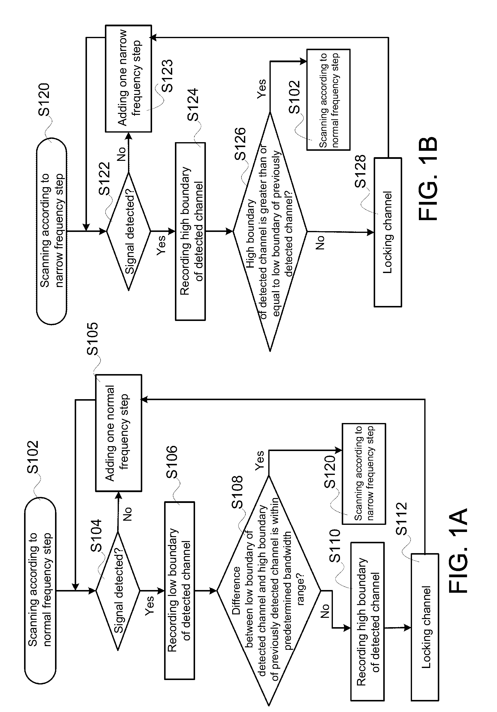
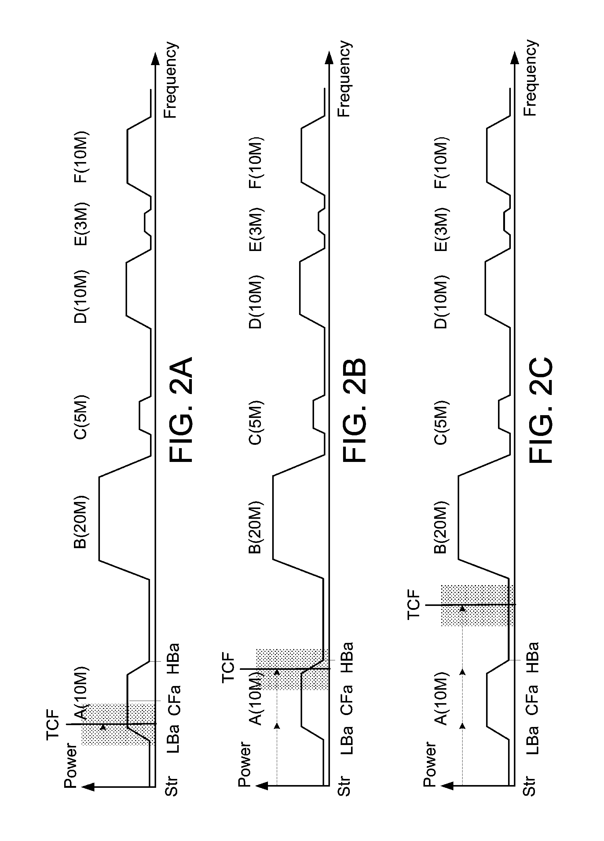
[0013]According to an embodiment of the present invention, in a DVB-S / S2 system, a process of channel scanning is first performed according to a normal frequency step (10 MHz). To prevent from missing certain channels during the process, when a channel is detected and a band between a low boundary of the detected channel and a high boundary of a previous detected channel is within a predetermined bandwidth range, the process returns to the high boundary of the previous detected channel, selectively adds a predetermined frequency (2 MHz), and the channel scanning is repetitively performed according to a narrow frequency step (3 MHz) until the high boundary of the detected channel is greater than the low boundary of the previous detected channel. The process continues to perform the channel scanning again according to the normal frequency step.

[0014]In contrast, when a channel is detected, and the band between the low boundary of the detected channel and the high boundary of the previ...


PUM


Abstract

A channel scanning method for Digital Video Broadcasting-Satellite (DVB-S) signals is provided. The method includes: scanning a radio frequency (RF) signal according to a normal frequency step; when the Nth channel is detected, obtaining a difference between a low boundary of an Nth channel and a high boundary of an (N−1)th channel; and, when the difference is within a predetermined bandwidth range, scanning the RF signal between the high boundary of the (N−1)th channel and the low boundary of the Nth channel according to a narrow frequency step. The normal frequency step is greater than the narrow frequency step.

Description

[0001]This application claims the benefit of Taiwan application Serial No. 101145305, filed Dec. 3, 2012, the subject matter of which is incorporated herein by reference.BACKGROUND OF THE INVENTION[0002]1. Field of the Invention[0003]The invention relates in general to a channel scanning method, and more particularly, to a channel scanning method for a Digital Video BroadcastingSatellite First Generation / Second Generation (DVB-S / S2) signals.[0004]2. Description of the Related Art[0005]In a Digital Video BroadcastingSatellite First Generation / Second Generation (DVB-S / S2) system, a center frequency and a symbol rate of a channel are unknown to a receiver. The symbol rate is a bandwidth of a channel. Due to differences in channel arrangements, channel scanning needs to be performed on radio frequency (RF) signals before viewing program contents carried by the RF signals.[0006]In other words, in a DVB-S / S2 system, after scanning and demodulating a channel of the RF signals, the receiv...

Claims


Application Information

Patent Timeline
Patent Type & Authority Patents(United States)
IPC IPC(8): H04N7/20H04H20/26H04H40/90H04N21/438H04N21/61
CPCH04N21/6193H04H40/90H04N21/4382H04N21/4383H04H20/26
Inventor CHANG, CHU-HSINCHENG, KAI-WENLIAO, YI-YINGLIN, TUNG-SHENGTUNG, TAI-LAI
Owner MEDIATEK INC
Learn More