40G/100G MSA-compliant optical transceivers with advanced functionality

a technology of optical transceivers and advanced functionality, applied in the field of optical and data networking, can solve problems such as limiting the performance of optical transceivers, and achieve the effect of transparent circuitry operation

Active Publication Date: 2015-01-06
LUMENTUM OPERATIONS LLC
View PDF19 Cites 6 Cited by
  • Summary
  • Abstract
  • Description
  • Claims
  • Application Information

AI Technical Summary

Benefits of technology

[0007]In another exemplary embodiment, a multi-source agreement (MSA) compliant optical transceiver includes an optical section including transmit optics and receive optics; an electrical section communicatively coupled to the optical section; circuitry in the electrical section configured to provide framing and forward error correction integrated within the MSA compliant optical transceiver and transparent to a host system housing the MSA compliant optical transceiver, wherein the host system is supports optical transceivers compliant to the MSA; a controller communicatively coupled to the optical section, the electrical section, and the host system; a housing compliant to the MSA, the housing containing the optical section, the electrical section, and the controller; and a communications port disposed on the housing and communicatively coupled to the controller, wherein the communications port is utilized to monitor and control operations, administration, maintenance, and provisioning (OAM&P) data associated with the circuitry thereby enabling a transparent manner of operation of the circuitry with respect to the host device.

Problems solved by technology

Advantageously, this enables interoperability among equipment vendors of optical transceivers, i.e. any MSA-compatible optical transceiver can be used in any host system designed to the MSA specification; however, these tightly defined characteristics limit the performance of optical transceivers since the MSA specifications were designed to maximize density and minimize cost, and not to provide advanced optical performance or other integrated functions.

Method used


Image

  • 40G/100G MSA-compliant optical transceivers with advanced functionality
  • 40G/100G MSA-compliant optical transceivers with advanced functionality
  • 40G/100G MSA-compliant optical transceivers with advanced functionality

Examples


Embodiment Construction

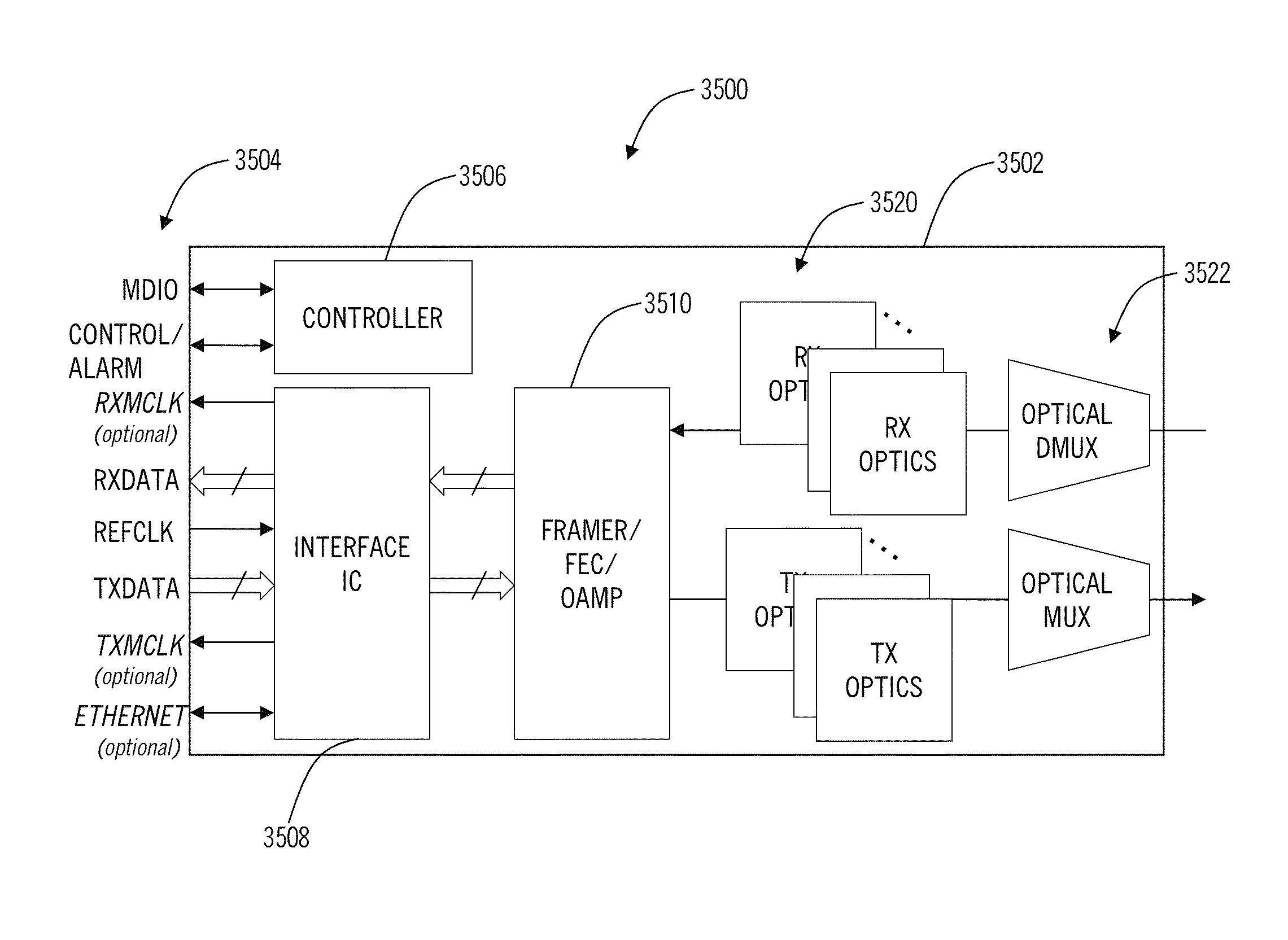
[0047]In various exemplary embodiments, the present disclosure provides integrated performance monitoring (PM); optical layer operations, administration, maintenance, and provisioning (OAM&P); alarming; and other advanced functionality in optical transceivers, such as multi-source agreement (MSA)-defined modules. The present disclosure provides an optical transceiver defined by an MSA agreement with integrated PM and alarming for carrier-grade operation. The integration preserves the existing MSA specifications allowing the optical transceiver to operate with any compliant MSA host device. Further, the host device can be configured through software to retrieve the PM and alarming from the optical transceiver. The optical transceiver can include CFP and variants thereof (e.g., future CFP2, CDFP, CXP), MSA-100GLH, CCRx, QSFP and variants thereof (e.g., future QSFP+, QSFP2), 10×10, XFP, XPAK, XENPAK, X2, XFP-E, SFP, SFP+, 300-pin, and the like.

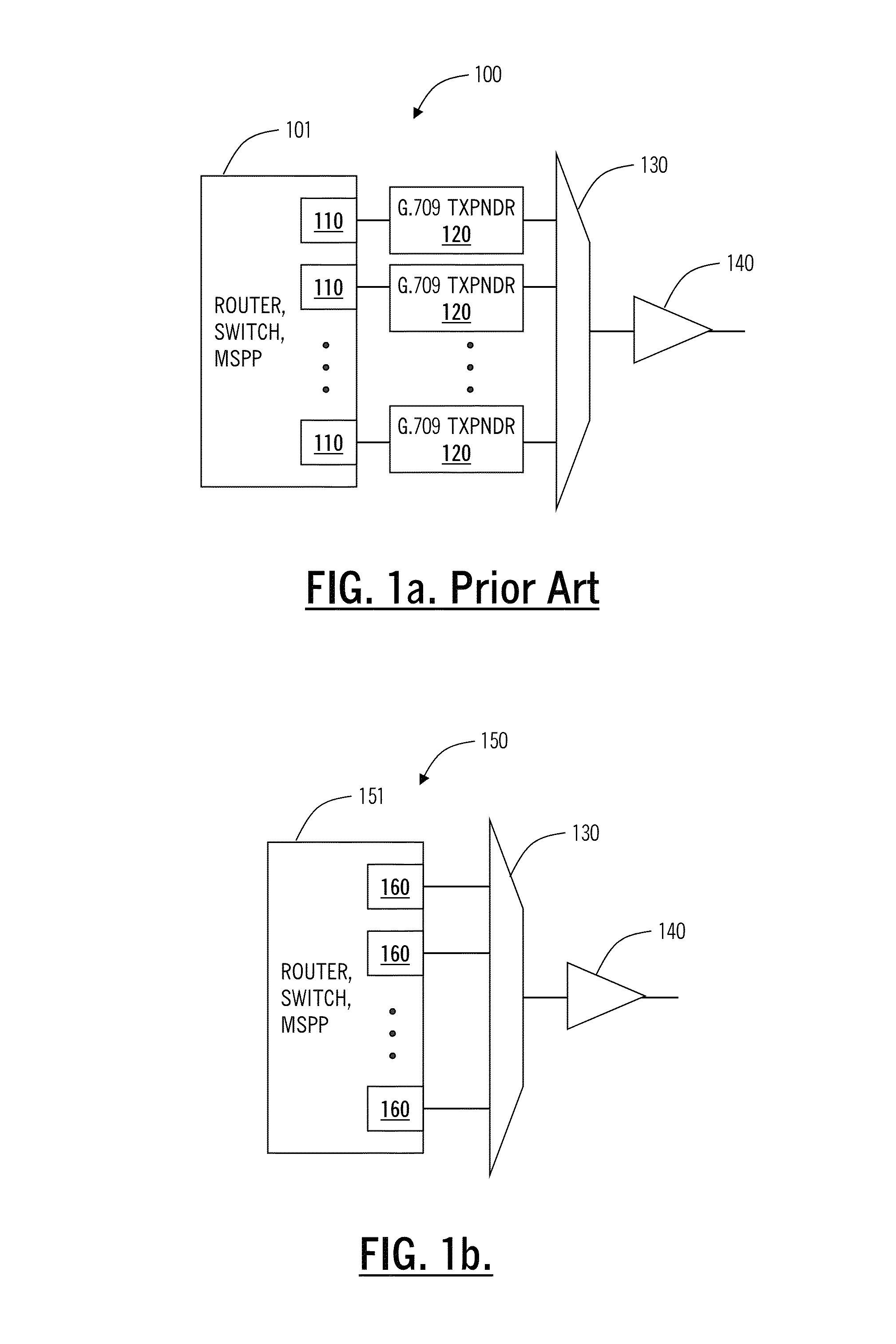
[0048]Referring to FIGS. 1a-1b, in exempla...


PUM


Abstract

Integrated performance monitoring (PM); optical layer operations, administration, maintenance, and provisioning (OAM&P); alarming; amplification, and the like is described in optical transceivers, such as multi-source agreement (MSA)-defined modules. An optical transceiver defined by an MSA agreement can include advanced integrated functions for carrier-grade operation which preserves the existing MSA specifications allowing the optical transceiver to operate with any compliant MSA host device with advanced features and functionality. The optical transceiver can include CFP and variants thereof (e.g., CFP2, CDFP, CXP), OIF-MSA-100GLH-EM-01.0, CCRx (Compact Coherent Receiver), Quad Small Form-factor Pluggable (QSFP) and variants thereof (e.g., QSFP+, QSFP2), 10×10 MSA, XFP, XPAK, XENPAK, X2, XFP-E, SFP, SFP+, 300-pin, and the like.

Description

CROSS-REFERENCE TO RELATED APPLICATION(S)[0001]This application is a continuation-in-part of co-pending U.S. patent application Ser. No. 13 / 025,947 filed Feb. 11, 2011, and entitled “40G / 100G OPTICAL TRANSCEIVERS WITH INTEGRATED FRAMING AND FORWARD ERROR CORRECTION,” which claims priority to U.S. patent application Ser. No. 12 / 120,149 filed May 13, 2008, and entitled “SYSTEMS AND METHODS FOR THE INTEGRATION OF FRAMING, OAM&P, AND FORWARD ERROR CORRECTION IN SFP OPTICAL TRANSCEIVER DEVICES,” which claims priority to U.S. Provisional Pat. Appl. No. 61 / 029,821, filed Feb. 19, 2008, and entitled “SYSTEMS AND METHODS FOR ETHERNET EXTENSION AND DEMARCATION,” and which claims priority as a continuation-in-part of U.S. Pat. No. 7,580,637, issued on Aug. 25, 2009, and entitled “SYSTEMS AND METHODS FOR THE INTEGRATION OF FRAMING, OAM&P, AND FORWARD ERROR CORRECTION IN PLUGGABLE OPTICAL TRANSCEIVER DEVICES,” all of which are incorporated in full by reference herein.FIELD OF THE DISCLOSURE[0002...

Claims


Application Information

Patent Timeline
Patent Type & Authority Patents(United States)
IPC IPC(8): H04B10/00G02B6/42H04B10/40H04J3/04H04L1/00
CPCH04B10/40H04L1/0057H04J3/047H04J2203/006H04J2203/0085G02B6/4284G02B6/4292
Inventor EL-AHMADI, SIRAJ NOUREL-AHMADI, SALAMHOTCHKISS, ADAM R.CARDONA, GABRIEL E.
Owner LUMENTUM OPERATIONS LLC
Why Eureka
Try Eureka