
Image processing apparatus and control method thereof

a control method and image processing technology, applied in the field of dynamic range extension technique, can solve the problems of image discontinuity, image discontinuity, image discontinuity, etc., and achieve the effect of avoiding image discontinuity in composition

Inactive Publication Date: 2014-10-21
CANON KK
View PDF5 Cites 8 Cited by
  • Summary
  • Abstract
  • Description
  • Claims
  • Application Information

AI Technical Summary

Benefits of technology

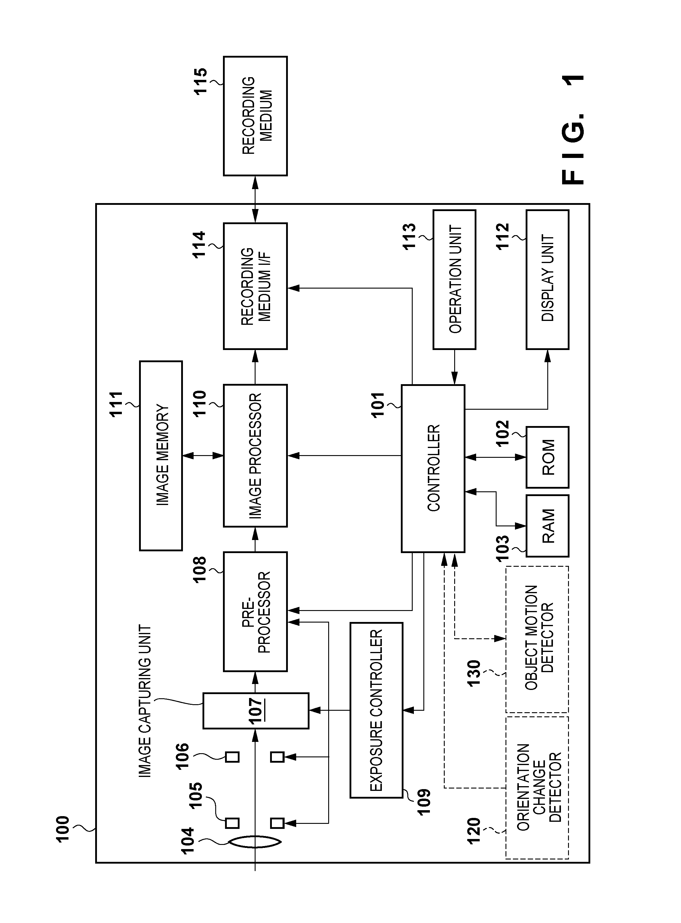
[0021]The present invention has been made in consideration of the problems of the conventional techniques. The present invention provides a technique which avoids image discontinuity in composition of a blown-out highlight region, halftone region, and shadow-detail loss region when a tone range is extended by compositing a plurality of differently exposed images.

Problems solved by technology

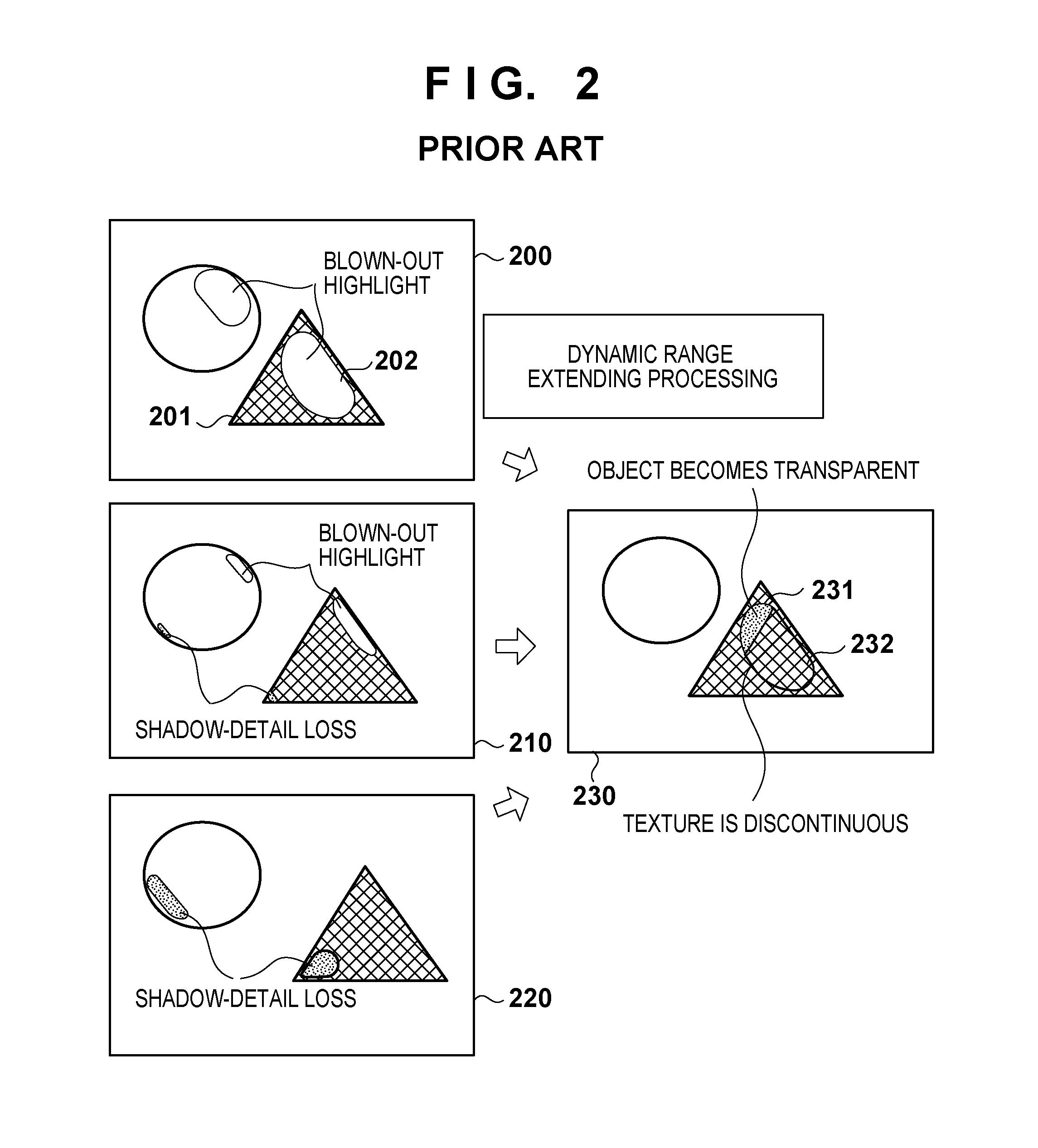
However, when objects include a moving object, images to be composited have different moving object regions, an image discontinuity problem occurs in an HDR image obtained by compositing the images to be composited.
More specifically, when object include a moving object, an HDR image obtained by compositing images obtained by a plurality of image capturing operations suffers the following problems associated with image discontinuity.
Not only image element replacement processing but also composition processing using weighted averaging of a plurality of images in a halftone range also cause image discontinuity such as multiple edges around a moving object and pattern mixture in added moving object regions as problems posed at the time of the conventional image composition processing.
However, the method of Japanese Patent Laid-Open No. 2002-101347 above has been proposed under the assumption of a case in which an image of a region (blown-out highlight region) having tone levels equal to or larger than a threshold in the overexposed image is replaced by the underexposed image, and does not consider any case in which the underexposed image includes a shadow-detail loss region.
That is, the aforementioned technique of Japanese Patent Laid-Open No. 2002-101347 eliminates image discontinuity in a blown-out highlight region, but it cannot simultaneously eliminate image discontinuity in all of a blown-out highlight region, halftone region, and shadow-detail loss region.
However, since this method requires hardware or processes for detecting motion vectors, other problems about an increase in circuit scale, that in processing time associated with calculations, and so forth may be posed.

Method used


Image

  • Image processing apparatus and control method thereof
  • Image processing apparatus and control method thereof
  • Image processing apparatus and control method thereof

Examples


first embodiment

[0035](First Embodiment)

[0036]A preferred embodiment of the present invention will be described in detail hereinafter with reference to the drawings. An embodiment to be described below will exemplify a case in which the present invention is applied to a digital camera, as an example of an image processing apparatus, which can output an image whose dynamic range is extended (HDR image) by compositing a plurality of images obtained by capturing images of an object to have different exposure times. However, the present invention is applicable to an arbitrary apparatus, which can output an image whose dynamic range is extended by compositing a plurality of images obtained by capturing images of an object to have different exposure times. In this specification, “image discontinuity” will generically express the aforementioned problems about transparency, texture discontinuity, image lag, multiple edges, and pattern mixture in an HDR image.

[0037](Functional Arrangement of Digital Camera)...

second embodiment

[0094](Second Embodiment)

[0095]The aforementioned first embodiment has explained the case in which as image elements corresponding to moving image elements in an HDR image, image elements of one image, in which the numbers of blown-out highlight and shadow-detail loss image elements are relatively small, of a plurality of differently exposed images are used. Therefore, in the first embodiment, image elements used as those corresponding to moving image elements of an HDR image are extracted from a common image throughout the HDR image. On the other hand, in an image processing apparatus of this embodiment, image elements corresponding to changes of objects are classified into groups, and an optimal exposed image is selected for each group to use image element values of the selected image as image elements of that group upon generation of an HDR image. A method of generating an image whose dynamic range is extended more in this way will be described below.

[0096](HDR Image Generation P...

first modification

[0118](First Modification)

[0119]The aforementioned first and second embodiments have explained the HDR image generation processing in consideration of object image blurs generated during image capturing operations of a plurality of differently exposed images. This modification will explain HDR image generation processing in consideration of the influence of a shake of the digital camera 100 (so-called camera shake), which is generated during image capturing operations of a plurality of differently exposed images, and is caused when the photographer holds the camera.

[0120]In the first modification, assume that the digital camera 100 includes an orientation change detector 120, which is configured by, for example, an acceleration sensor or at least one of an acceleration sensor and geomagnetism sensor. The orientation change detector 120 obtains orientation changes of the digital camera 100 during image capturing operations of a plurality of differently exposed images, and informs the...


PUM


Abstract

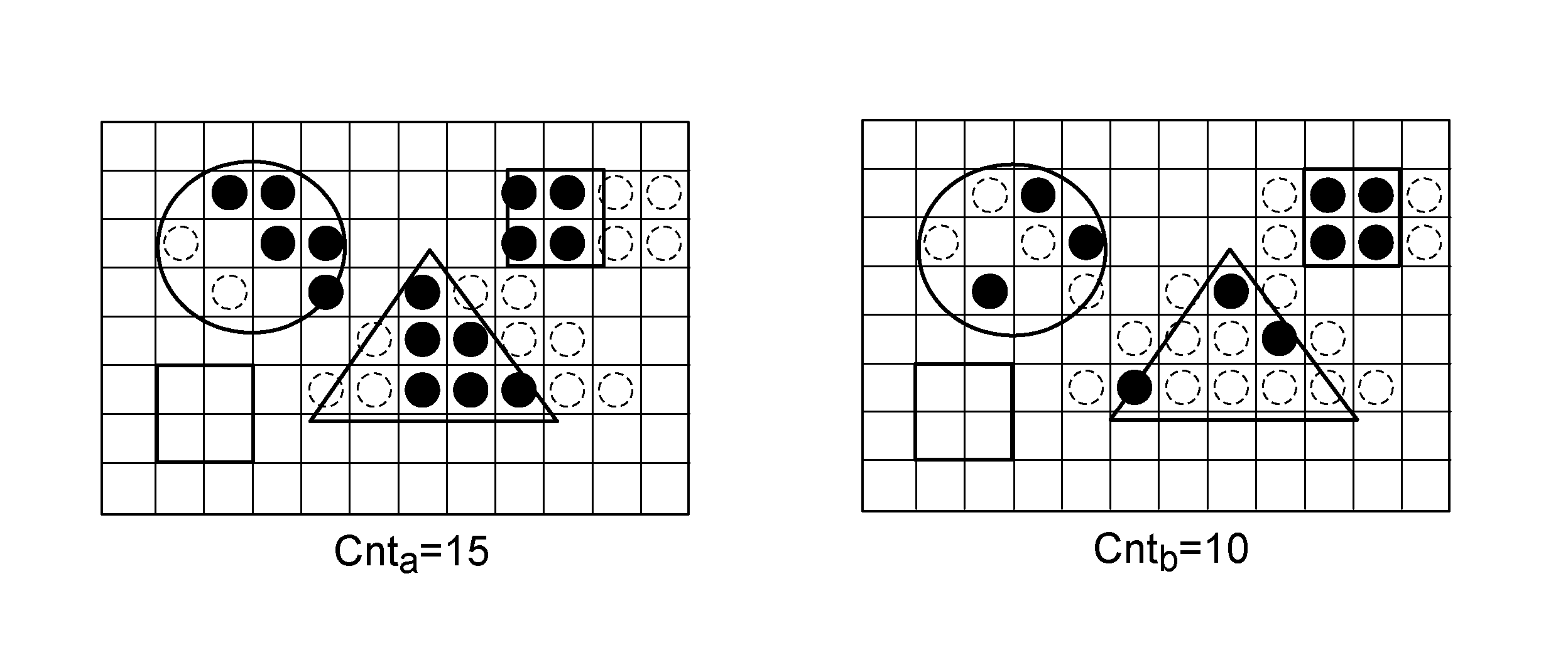
After a plurality of differently exposed images are obtained, and tone levels of the plurality of images are adjusted, image elements corresponding to changes of objects are detected based on pixel value differences between the plurality of images. Then, the numbers of blown-out highlight and shadow-detail loss image elements in the image elements corresponding to the changes of the objects are counted for the plurality of images. Then, an image in which the total of the numbers of image elements is smallest is selected. Furthermore, image elements corresponding to the changes of the objects in the selected image are used as those corresponding to image elements corresponding to the changes of the objects in an HDR image to be generated.

Description

BACKGROUND OF THE INVENTION[0001]1. Field of the Invention[0002]The present invention relates to a dynamic range extending technique for extending a tone range by compositing a plurality of differently exposed images.[0003]2. Description of the Related Art[0004]In recent years, some of image capturing apparatuses such as digital cameras and digital video cameras have a dynamic range extending function which obtains an image whose tone range is extended by compositing a plurality of differently exposed images, which are obtained by capturing images of an object using different exposure times.[0005]A basic concept of a dynamic range extending technique, that is, a so-called HDR (High Dynamic Range) image generation technique, used in the dynamic range extending function is as follows.[0006]Image elements of a blown-out highlight region in an overexposed image are compensated for from those of images captured to have shorter exposure times than that image.[0007]Image elements of a shad...

Claims


Application Information

Patent Timeline
Patent Type & Authority Patents(United States)
IPC IPC(8): G06T5/50G06T5/00H04N5/235H04N5/355
CPCH04N5/2356G06T2207/20208H04N5/35572G06T2207/10144H04N5/2355H04N5/2353G06T5/008G06T5/50H04N23/743H04N23/73H04N23/741H04N25/587
Inventor TSUBAKI, HIDETOSHI
Owner CANON KK
Learn More