
Reversible peristaltic pump and other structures for reflux in eye surgery

a peristaltic pump and reflux technology, applied in the field of control of surgical fluid flow, can solve the problems of significant tissue damage, excessive pressure within the eye may strain and injure eye tissues, impeding the flow of material and fluids, etc., and achieve the effect of clear occlusion

Active Publication Date: 2014-10-07
JOHNSON & JOHNSON SURGICAL VISION INC
View PDF10 Cites 14 Cited by
  • Summary
  • Abstract
  • Description
  • Claims
  • Application Information

AI Technical Summary

Benefits of technology

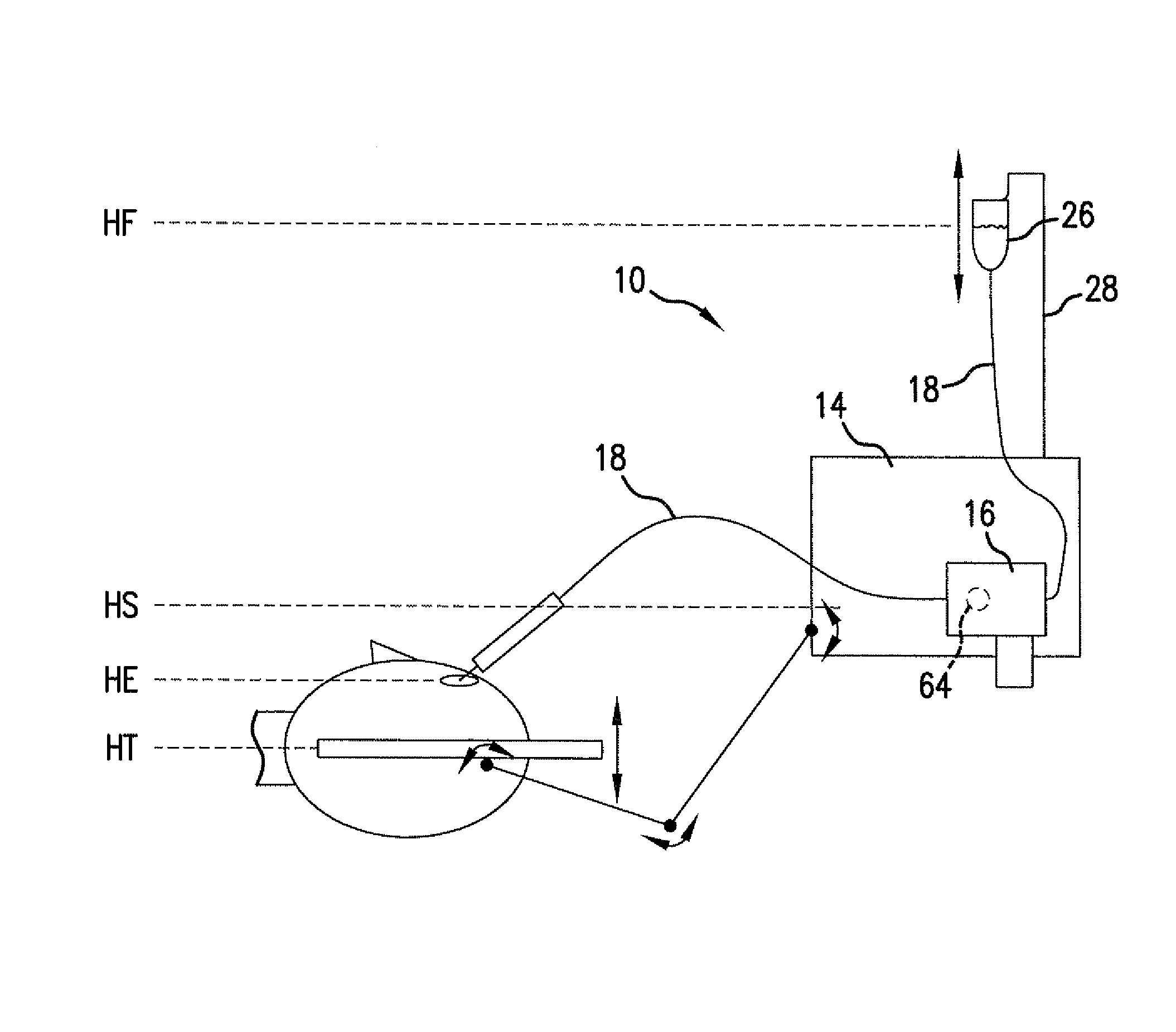
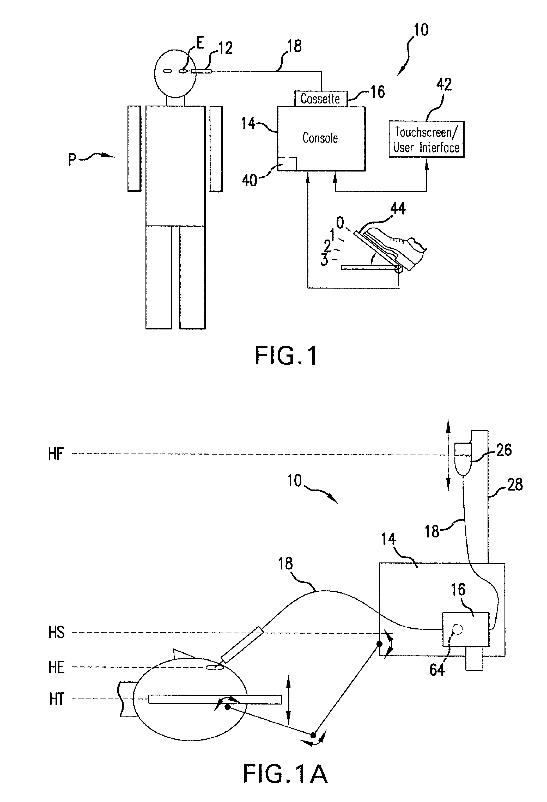
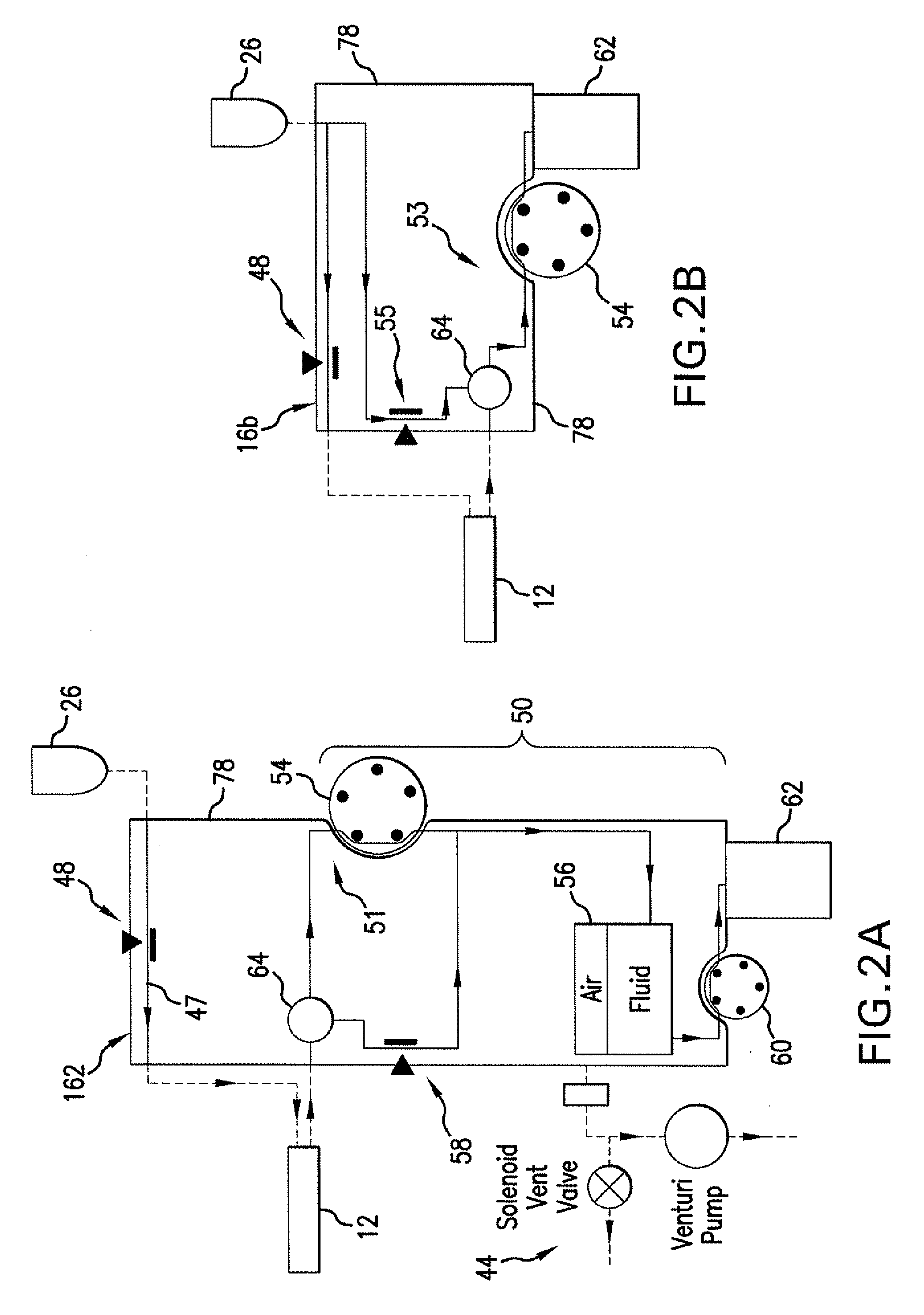
[0009]In a first aspect, the invention provides an eye treatment method comprising directing an irrigation flow into the eye through an irrigation conduit pathway. Material is aspirated from within the eye by drawing an aspiration flow through an aspiration conduit pathway with a pump. In response to a user request and / or an occlusion of the aspiration flow, the pump is reversed and fluid is pumped back into the aspiration conduit pathway, for example, to reflux flow into the eye to help clear the occlusion.
[0015]In another aspect, the invention provides an eye treatment method comprising directing an irrigation flow into the eye through an irrigation conduit pathway. Material is aspirated from within the eye by drawing an aspiration flow through an aspiration conduit pathway. In response to an occlusion of the aspiration flow (the occlusion typically inducing a compliant reduction in volume of the aspiration conduit pathway), fluid may be introduced into the aspiration conduit pathway. The introduction of fluid into the aspiration conduit pathway may be controlled in response to a pressure along the aspiration conduit pathway so that a maximum reflux pressure within the aspiration conduit pathway adjacent the eye is less than, or substantially equal to, an irrigation flow pressure adjacent the eye or some other predetermined pressure. As a result, reflux into the eye is generated at least in part by momentum in the aspiration conduit pathway toward the eye.
[0017]In another aspect, the invention provides an eye treatment system comprising an eye treatment probe and an eye treatment console having a processor and an aspiration pump drive. A cassette couples the probe to the processor and / or console. The cassette has a pressure sensor disposed along an irrigation conduit pathway for determining an irrigation flow pressure into the eye via the probe. The cassette and probe have an aspiration conduit pathway coupled to the pump for aspirating material from within the eye. The processor of the console is configured to reverse the pump to reflux fluid from the aspiration conduit pathway and into the eye to help clear occlusions.

Problems solved by technology

If the total volume of fluid in the eye is allowed to get too low at any time during the procedure, the eye may collapse and cause significant tissue damage.
Similarly, excessive pressure within the eye may strain and injure tissues of the eye.
Unfortunately, larger and / or harder tissue particles may at least temporarily cover the aspiration port of the probe, impeding flow of material and fluids from the eye into the probe.
Unfortunately, significant fluid pressure transients can occur during this process.
While existing eye treatment systems have structures that can successfully clear many or all occlusions, known occlusion clearing approaches may actually increase pressure transients, and / or may rely on complex and costly system components.
More generally, current occlusion clearing methodologies may have either a relatively slow response time or insufficient pressure control.

Method used


Image

  • Reversible peristaltic pump and other structures for reflux in eye surgery
  • Reversible peristaltic pump and other structures for reflux in eye surgery
  • Reversible peristaltic pump and other structures for reflux in eye surgery

Examples


Embodiment Construction

[0030]The present invention generally provides improved devices, systems, and methods for treating an eye of a patient. Exemplary embodiments provide improved techniques for directing fluids into an aspiration conduit pathway between an eye and an eye treatment console for clearing occlusions and the like, particularly during treatments within an interior of the eye.

[0031]In many embodiments, an eye treatment probe handpiece will be coupled to an eye treatment console by a cassette mounted to the console. The cassette may include a surgical fluid network, typically including an irrigation conduit pathway for directing irrigation fluid toward the eye and an aspiration conduit pathway for directing material (typically including both fluid and tissue) from the eye. The fluid network of the cassette may include resiliently deformable tubing, flexible (but less compressible or expandable) tubing, a pressure sensing mechanism, a holding tank or chamber, and / or the like. The cassette and c...


PUM


Abstract

Devices, systems, and methods for treatment of an eye alter aspiration flow from the eye in response to an occlusion of the aspiration conduit pathway. Where aspiration is drawn from the eye using a volumetric pump, the pump can be reversed so as to induce fluid reflux from the aspiration conduit pathway into the eye to help clear the occlusion. The pump may vary the reverse flow in response to sensed aspiration pressure or the like, and the reverse flow may be halted before the pressure within the aspiration conduit pathway adjacent the eye significantly exceeds the irrigation fluid pressure and / or the pressure within the eye. Reflux may alternatively be generated by modulating a vent valve disposed between an irrigation conduit pathway and the aspiration conduit pathway.

Description

RELATED APPLICATION[0001]The present application claims priority under 35 U.S.C §119(e) to provisional application No. 60 / 865,163, filed on Nov. 9, 2006 under the same title. Full Paris Convention priority is hereby expressly reserved.BACKGROUND OF THE INVENTION[0002]The present invention is generally related to methods, devices, and systems for controlling surgical fluid flows, often during treatments of an eye. In exemplary embodiments, the invention allows clearing of an occlusion in an aspiration conduit pathway during (for example) cataract surgery or the like, optionally by reversing a peristaltic aspiration pump, modulating a vent valve between the aspiration conduit pathway and an irrigation fluid source, or the like.[0003]With age, clouding of the lens or cataracts are fairly common. Cataracts may form in the hard central nucleus of the lens, in the softer peripheral cortical portion of the lens, or at the back of the lens near the capsular bag. Cataracts can be treated by ...

Claims


Application Information

Patent Timeline
Patent Type & Authority Patents(United States)
IPC IPC(8): A61M1/00
CPCA61M1/0031A61M1/0033A61M2205/3351A61M1/0058A61M2205/12A61M2210/0612A61M1/0074A61M3/0283A61M1/0025A61F9/00745A61M2205/3334A61M1/742A61M1/74A61M1/774A61M3/0201A61M3/0202A61M1/77A61M1/72A61M1/73A61M1/802
Inventor KING, DAVIDMURI, JOHN I.SUTTON, THOMAS B.
Owner JOHNSON & JOHNSON SURGICAL VISION INC
Learn More