
Golf club shaft

a golf club and shaft technology, applied in the field of golf club shafts, can solve the problems of increasing shaft weight and reducing the strength of the grip portion, and achieve the effect of suppressing the flexural rigidity of the grip portion and achieving excellent strength

Active Publication Date: 2014-09-09
SUMITOMO RUBBER IND LTD
View PDF10 Cites 8 Cited by
  • Summary
  • Abstract
  • Description
  • Claims
  • Application Information

AI Technical Summary

Benefits of technology

The present invention aims to provide a lightweight golf club shaft that is strong and has high operativity. It achieves this by suppressing the flexural rigidity of the grip portion and maintaining the strength of the grip. This results in a shaft that is lightweight but still has excellent strength.

Problems solved by technology

However, the constitution is apt to reduce the strength of the grip portion.
However, in this case, a shaft weight is increased.

Method used


Image

  • Golf club shaft
  • Golf club shaft
  • Golf club shaft

Examples


example 1

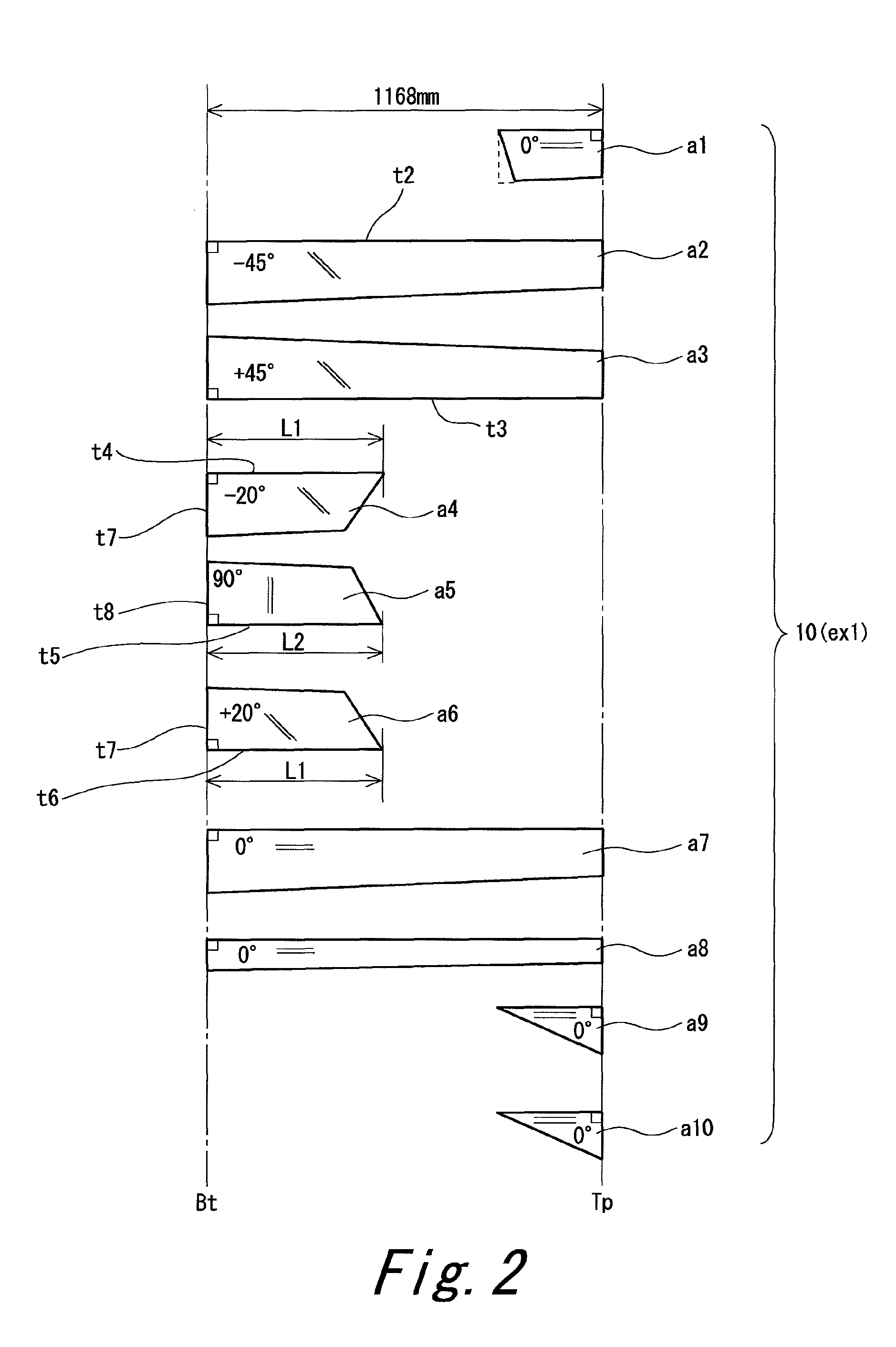
[0120]A shaft having the same laminate constitution as that of the shaft 6 was produced. That is, a shaft having a sheet constitution shown in FIG. 2 was produced. A manufacturing method was the same as that of the shaft 6. A united sheet a456 shown in FIG. 3 was used.

[0121]In example 1, the product name and the number of windings of each sheet were as follows. The specifications of these products are shown in Table 1 described above.[0122]Sheet a1: TR350C-150S (two plies)[0123]Sheet a2: MR350C-100S (two plies)[0124]Sheet a3: MR350C-100S (two plies)[0125]Sheet a4: 2256S-12 (two plies)[0126]Sheet a5: 805S-3 (two plies)[0127]Sheet a6: 2256S-12 (two plies)[0128]Sheet a7: MR350C-100S (two plies)[0129]Sheet a8: MR350C-100S (one ply)[0130]Sheet a9: TR350C-100S[0131]Sheet a10: TR350C-100S

[0132]A commercially available driver head (New XXIO (2011 model) manufactured by SRI Sports Limited.: loft 10.5 degrees) and grip were attached to the obtained shaft, to obtain a golf club according to ex...

example 2

[0133]FIG. 4 shows a laminate constitution of a shaft according to example 2. In example 2, the product name and the number of windings of each sheet were as follows.[0134]Sheet a1: TR350C-150S (two plies)[0135]Sheet a2: MR350C-100S (two plies)[0136]Sheet a3: MR350C-100S (two plies)[0137]Sheet a4: 2256S-12 (two plies)[0138]Sheet a5: 805S-3 (two plies)[0139]Sheet a6: 2256S-12 (two plies)[0140]Sheet a7: MR350C-100S (two plies)[0141]Sheet a8: MR350C-100S (one ply)[0142]Sheet a9: TR350C-100S[0143]Sheet a10: TR350C-100S

[0144]A shaft and a golf club according to example 2 were obtained in the same manner as in example 1 except for above.

example 3

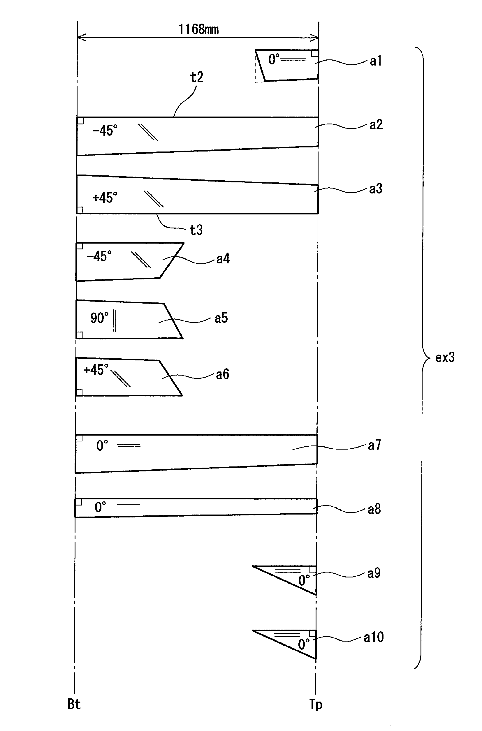
[0145]FIG. 5 shows a laminate constitution of a shaft according to example 3. In example 3, the product name and the number of windings of each sheet were as follows.[0146]Sheet a1: TR350C-150S (two plies)[0147]Sheet a2: MR350C-100S (two plies)[0148]Sheet a3: MR350C-100S (two plies)[0149]Sheet a4: 2256S-12 (two plies)[0150]Sheet a5: 805S-3 (two plies)[0151]Sheet a6: 2256S-12 (two plies)[0152]Sheet a7: MR350C-100S (two plies)[0153]Sheet a8: MR350C-100S (one ply)[0154]Sheet a9: TR350C-100S[0155]Sheet a10: TR350C-100S

[0156]A shaft and a golf club according to example 3 were obtained in the same manner as in example 1 except for above.


PUM


Abstract

A shaft 6 has a plurality of layers a1 to a10. The layers include a bias layer in which an absolute angle θa of a fiber to a shaft axis line is 10 degrees or greater and 70 degrees or less, and a hoop layer in which the angle θa is equal to or greater than 80 degrees. The layers include a full length layer disposed all over in an axis direction of the shaft, and a partial layer partially disposed in the axis direction of the shaft. The partial layer includes back end reinforcing bias layers a4 and a6, and a backend reinforcing hoop layer a5. In the shaft 6, a torsional rigidity value GIt at a point separated by 300 mm from a butt end is 3.5×10⁶ (kgf·mm2 / deg) or greater and 5.0×10⁶ (kgf·mm2 / deg) or less.

Description

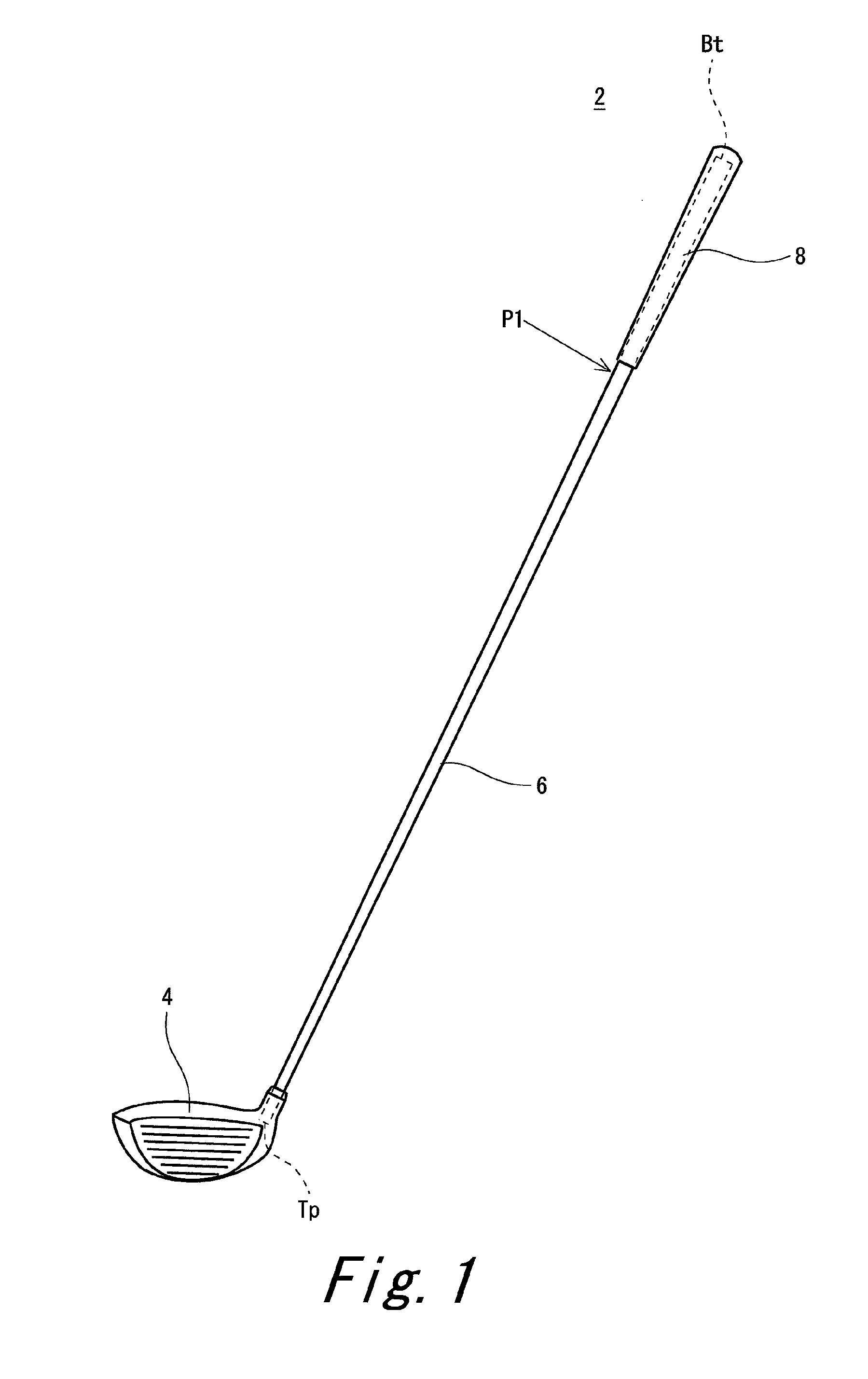
[0001]The present application claims priority on Patent Application No. 2011-121471 filed in JAPAN on May 31, 2011, the entire contents of which are hereby incorporated by reference.BACKGROUND OF THE INVENTION[0002]1. Field of the Invention[0003]The present invention relates to a golf club shaft.[0004]2. Description of the Related Art[0005]Flex point is known as one of specifications of a golf club shaft. High flex point, middle flex point, and low flex point are known as the flex point.[0006]A shaft having high flex point can suppress an unstable motion of the tip part of the shaft. The shaft having high flex point has excellent operativity and small variation in a hit ball.[0007]Japanese Patent Application Laid-Open No. 9-234256 discloses a golf club shaft which has a grip portion and a tip portion having higher torsional rigidity in a torsional rigidity distribution property line compared to a case the torsional rigidity distribution property line is drawn by a straight line. The...

Claims


Application Information

Patent Timeline
Patent Type & Authority Patents(United States)
IPC IPC(8): A63B53/10A63B102/32
CPCA63B53/10A63B2209/02A63B60/42
Inventor NAKANO, TAKASHI
Owner SUMITOMO RUBBER IND LTD
Learn More