
Flexible surgical stapler with motor in the head

a flexible, surgical technology, applied in the field of flexible surgical staplers, can solve the problems of limiting the ability to manipulate the staple assembly, limiting the range of flexibility between the staple assembly and the associated handle,

Active Publication Date: 2014-09-09
COVIDIEN LP
View PDF71 Cites 1270 Cited by
  • Summary
  • Abstract
  • Description
  • Claims
  • Application Information

AI Technical Summary

Problems solved by technology

This may limit the ability to manipulate the staple assembly relative to the tissue desired to be operated upon.
However, these devices still limit the range of flexibility between the staple assembly and the associated handle.

Method used


Image

  • Flexible surgical stapler with motor in the head
  • Flexible surgical stapler with motor in the head
  • Flexible surgical stapler with motor in the head

Examples


Embodiment Construction

[0062]Embodiments of the presently disclosed remote motorized stapler heads and surgical staplers will now be described in detail with reference to the drawings wherein like numerals designate identical or corresponding elements in each of the several views. As is common in the art, the term “proximal” refers to that part or component closer to the user or operator, i.e. surgeon or physician, while the term “distal” refers to that part or component further away from the user.

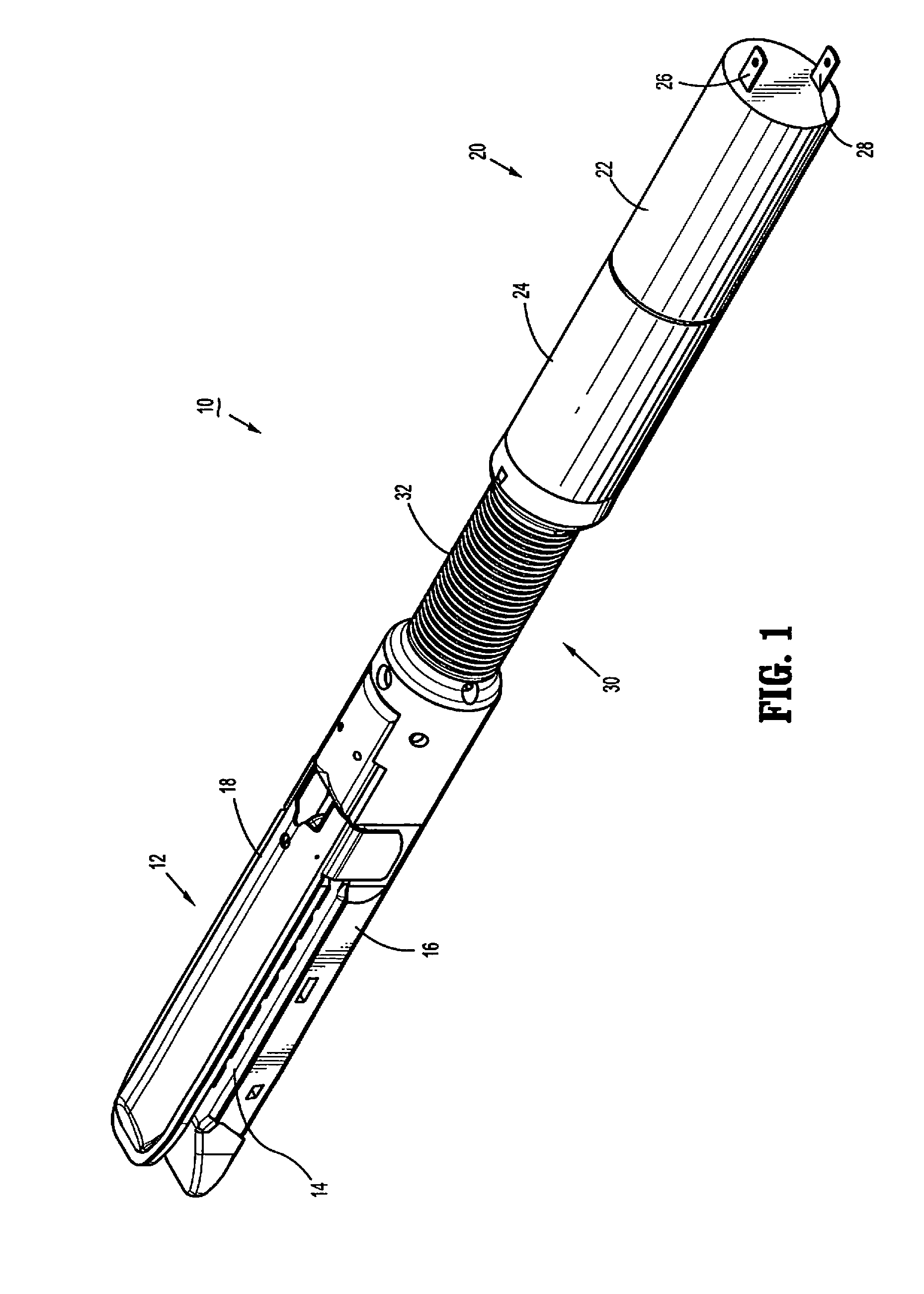
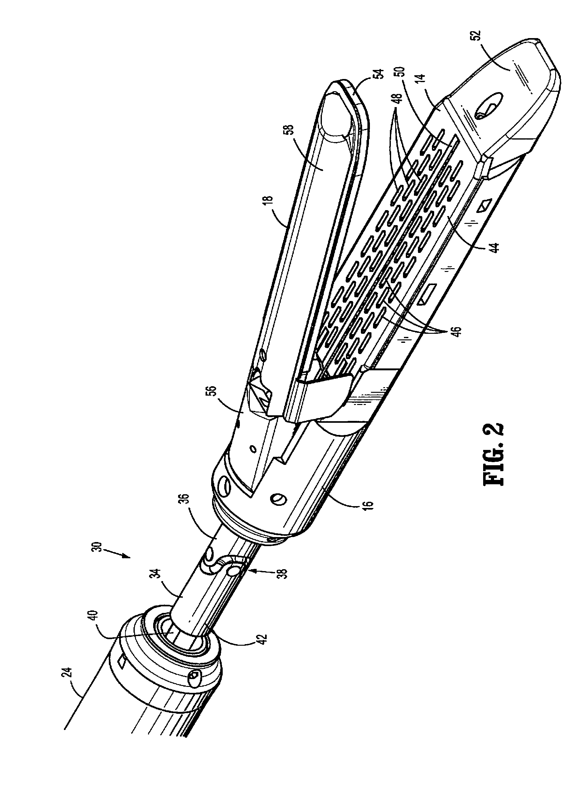
[0063]Referring to FIGS. 1-6, and initially to FIG. 1, there is disclosed a remote, motorized stapler head 10 for use in a surgical instrument. Stapler head 10 is provided to enhance the flexibility of a surgical stapler when used in various areas of the body and is designed to be inserted through a cannula. Stapler head 10 can then be manipulated within the body while the actuating mechanism (not shown) remains outside the body. Stapler head 10 is connected to the actuating mechanism by a pair of highly flexibl...


PUM

PropertyMeasurementUnit
flexibleaaaaaaaaaa
flexibilityaaaaaaaaaa
degree of flexibilityaaaaaaaaaa

Abstract

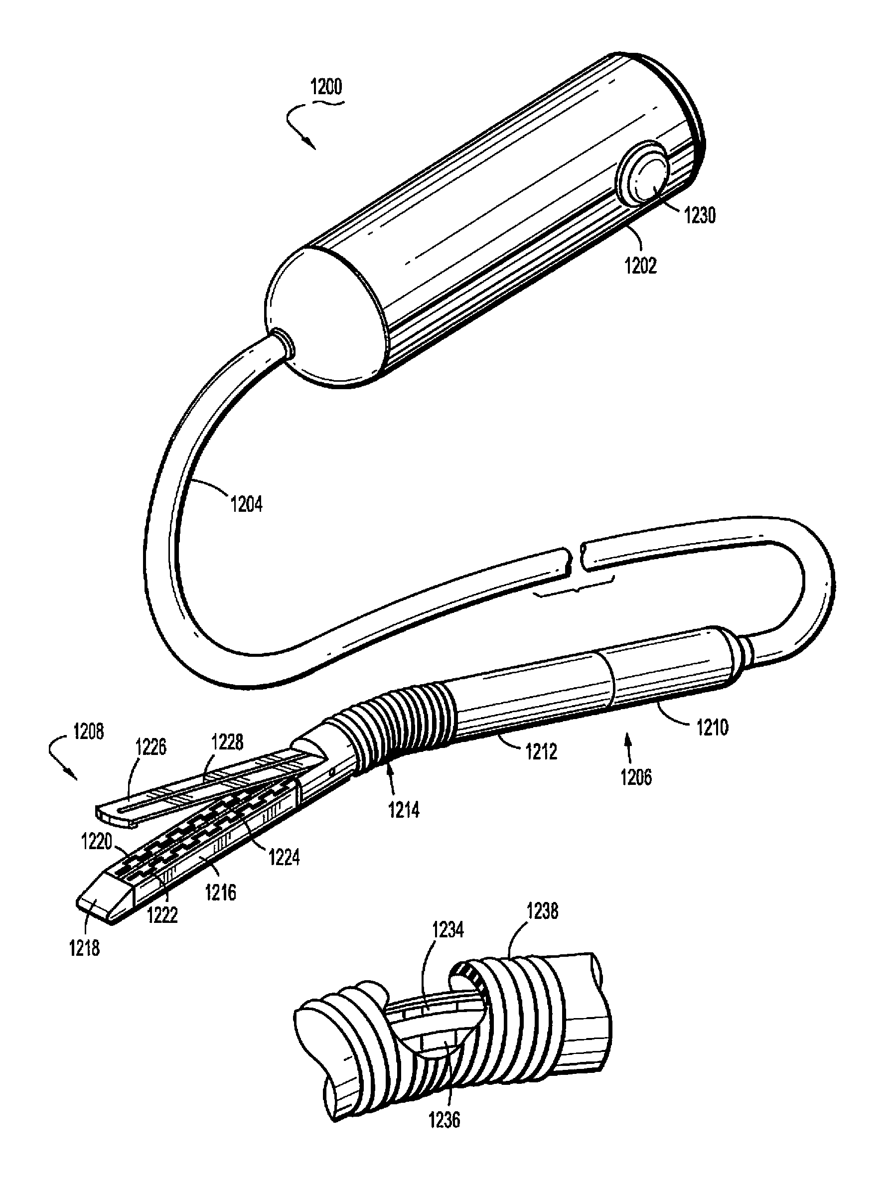
A surgical stapler having a remote motorized staple head is provided and generally includes a handle having a control button and a highly flexible cable extending distally from the handle. A housing incorporating a staple assembly is affixed to a distal end of the flexible cable. The housing may incorporate articulating structure to position the staple assembly relative to the remainder of the housing.

Description

CROSS-REFERENCE TO RELATED APPLICATIONS[0001]The present application claims priority to, and the benefit of, U.S. Provisional Application Ser. No. 61 / 218,489 filed Jun. 19, 2009, the entire contents of which are hereby incorporated by reference.BACKGROUND[0002]1. Technical Field[0003]The present disclosure relates to flexible surgical staplers having a motor in the end effector. More particularly, the present disclosure relates to flexible surgical staplers having a highly flexible cable between an actuator and stapler driving motor located in the stapler head.[0004]2. Background of Related Art[0005]Various surgical stapling devices are known in the art which are designed to be passed through a port and into a body cavity to perform a stapling procedure on tissue. These devices generally include a handle having a rigid elongate member extending distally therefrom. A staple assembly is provided on the distal end of the elongate member to staple tissue and sever the tissue between row...

Claims


Application Information

Patent Timeline
Patent Type & Authority Patents(United States)
IPC IPC(8): A61B17/04A61B17/10A61B17/00A61B17/072A61B17/29
CPCA61B17/07207A61B2017/2927A61B2017/003A61B2017/2905A61B2017/00398A61B2017/00022A61B2017/07278A61B2017/00017A61B2017/00327A61B2017/00309A61B2017/2932A61B2017/07271A61B2017/00433A61B17/068
Inventor VIOLA, FRANKBEARDSLEY, JOHN W.BRYANT, TEDDY R.
Owner COVIDIEN LP
Learn More